
Ducati Diavel Service Manual: Refitting the oil pump
If removed, apply specific threadlocker on the bushing (7) outer thread, and screw it in the crankcase half, observing the height.
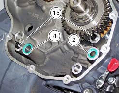
Position the reference bushings (15) and the oil sealing o-rings (2) and (4) according to the crankcase lubrication channels.
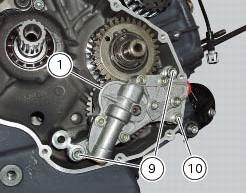
Position the oil pump on the crankcase and tighten screws (9) to a torque of 26 nm (min. 23 Nm - max. 29 Nm) and the screw (10) to a torque of 10 nm (min. 9 Nm - max. 11 Nm) (sect. 3 - 3, Engine torque settings).
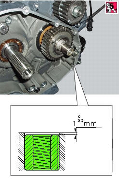
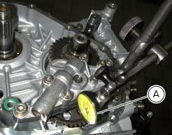
Check the gear clearance with the driving pinion by fixing a dial gauge (a), equipped with the appropriate traces, to the crankcase half.
Position the dial gauge stylus on one tooth of oil pump gear and set the gauge to zero in this position.
Move the gear slightly to measure the backlash; take four readings in diametrically opposed positions of the gear.
The clearance should be 0.10 Mm.
 Reassembly of the oil pump
Check that the circlip (3) and tongue (13) are present on the pump.
Fit the pump drive gear (12) on to the oil pump and secure it by installing the
circlip (6) in its groove.
Insert the by-p ...
 Oil cooler
Oil cooler
Vibration damper mount
Spacer
Screw
Nipple
Aluminium gasket
Oil delivery hose
Screw
Plate
Bracket
Screw
Engine oil pressure sensor
Sealing washer
Heat guard ...
Other materials:
Removal of the fuel tank fairings
Remove the rh air inlet (7) by loosening screws (6) and (9).
Undo the retaining screw (3) of the rh front half-fairing (1).
Slightly pull the pin (a) to disengage it from the seal (b), and remove the
rh front half-fairing (1) by sliding it onwards
and releasing the tabs (c) from the ...
Removal of the gearchange control
Loosen and remove the pivot screw (4) securing the gearchange pedal (1) and
recover the washer (9) and the o-ring Seals (5).
Loosen and remove the screw (7) securing the gearchange lever (8) to the gear
selector shaft.
Withdraw the lever (8) complete with the gearchange control assem ...
Dashboard
Note
The dashboard is supplied as a single component; its internal components
cannot be renewed separately.
Important
Whenever the dashboard is renewed, the ignition key programming procedure
must be repeated.
Loosen the nuts (2) to remove the master dashboard (1) from its seat and
disconn ...