
Ducati Diavel Service Manual: Refitting the primary drive gears and checking backlash
Fully degrease the crankshaft splined end and the corresponding spline on the primary drive gear.
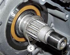
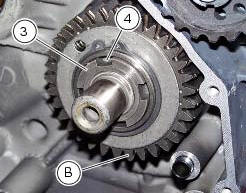
Position the spacer (c) onto the crankshaft.
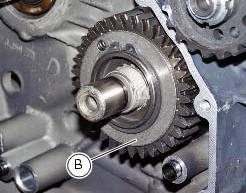
Fit the driving gear (b) onto the crankshaft with the oil pump drive sprocket facing the crankcase.
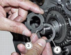
Temporarily secure the gear with the washer (4) and nut (3).
Important
If fitting a new primary driving gear (b), check the backlash.
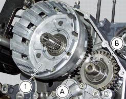
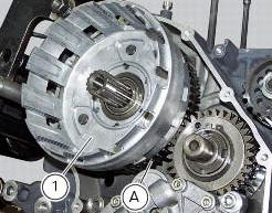
To check the clearance, temporarily fit the clutch bell (1) complete with the primary driven gear (a) on the gearbox primary shaft. Fix a dial gauge to the engine crankcase, positioning the stylus against a gear tooth.
Turn the driven gear (a) to mesh the teeth and check that clearance ranges between 0.05 And 0.07 Mm.
Repeat the check at 16 different points of the driven gear.
If the measured values are outside the permissible tolerance limits, try changing the position of driven gear (a) on the primary shaft, leaving the driving gear (b) on the crankshaft. If still outside tolerance values, renew the whole primary drive gear pair.
After checking backlash, fit the bush 88713.3406 On a torque wrench, lock the pinion (b) with the holding tool 88713.3417.
Position the washer (4) and the ring nut (3). Use the special tool 88713.3406 To tighten the ring nut (3) to a torque of 190 nm (min. 171 Nm - max. 209 Nm) (sect. 3 - 3, Engine torque settings).
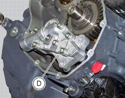
Refit the oil pump (d) and check the clearance between the oil pump gear and primary drive gear on the crankshaft (sect. 9 - 2.1, Refitting the oil pump).
Thoroughly degrease the mating surfaces of the clutch bell (1).
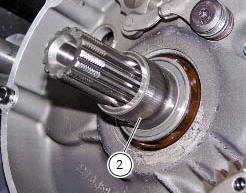
Fit the spacer (2) onto the primary shaft. Fit the clutch housing (1) along with the driven gear (a).
 Removal of the primary drive gear
Withdraw the clutch housing (1) complete with driven gear of the primary pair
(a).
Remove the inner spacer (2).
Remove the oil pump (d) (sect. 9 - 2.1, Removal of the oil pump).
L ...
 Gearbox assembly
...
Other materials:
Refitting the rear wheel
Lubricate the wheel shaft threaded end with prescribed grease.
Insert the wheel shaft by matching (a) with pins (b).
Install spacer (3) with the conical surface faced to the wheel conical
surface, washer (2), apply prescribed grease to nut
(1) and insert it by hand (1).
Tighten the ...
Dashboard
Note
The dashboard is supplied as a single component; its internal components
cannot be renewed separately.
Important
Whenever the dashboard is renewed, the ignition key programming procedure
must be repeated.
Loosen the nuts (2) to remove the master dashboard (1) from its seat and
disconn ...
Refitting the front brake system
While refitting the system, pay special attention to the orientation of the
pipe couplings (24) on the pump and the pipes
(13) and (20) on the callipers (9) and (18).
Warning
If incorrectly positioned, the hose can affect brake operation and
foul moving parts. Position the hose as shown in th ...