
Ducati Diavel Service Manual: Refitting the rear brake calliper
When replacing the brake pipes (33) or removing one of the rear braking system components, pay special attention to the position of the couplings on the pump and the calliper.
Warning
If incorrectly positioned, the hose can affect brake operation and foul moving parts. Position the hose as shown in the figure.
Remember to fit the copper faced sealing washers (23) to the hose end fitting when reconnecting the brake pipe to the brake calliper (15).
After orientating the fitting, lock the special screw (22) to a torque of 23 nm +/- 10% (sect. 3 - 3, Frame torque settings).
If the speed sensor (1) was removed, fit it on the calliper holder bracket (a) with the spacer (8) and the washer (32) and tighten the screw (2) to a torque of 10 nm +/- 10% (sect. 3 - 3, Frame torque settings).
Note
The gap between the sensor (1) and the brake disc fixing screw must be within 0.6 To 2.2 Mm.
If it is necessary to remove the calliper holder bracket (a) in order to refit it, see sec. 7 - 13, Refitting the rear wheel eccentric hub and rear wheel shaft.
Insert the rear brake calliper (15) on the brake disk, aligning it with the holes of the calliper mounting bracket (a).
Grease the screws (12) and tighten to the torque of 25 nm +/- 5% (sect. 3 - 3, Frame torque settings).
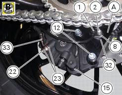
In order to fit the pipe (33), the speed sensor (1) and the retaining clamps follow instructions in sect. 7-6, Flexible wiring/hoses positioning.
 Removal of the rear brake disc
Remove the rear eccentric hub (sec. 7 - 13, Removal of the rear wheel
eccentric hub and rear wheel shaft).
Undo and remove the four fixing screws (13) of the brake disk to the wheel axle
and re ...

Other materials:
Warning indication (alarms/signals)
The instrument panel activates in real-time some warnings /
malfunction that are not dangerous for the correct operation
of the vehicle.
At key-on (at the end of the check) one or more "warnings"
are displayed if they are active.
When a "warning" is triggered, the indica ...
California emission control warranty statement
Your warranty rights and obligations
The california air resources board is pleased to explain the
emission control system warranty on your my 2011
motorcycle. In california, new motor vehicles must be
designated, built and equipped to meet the state's stringent
anti-smog standards. Ducati north ...
Routing of wiring on frame
The routing of the wiring has been optimised to ensure the minimum
obstruction.
Each section is designed to prevent interference with parts that might damage
wires or cause operating failures when
riding. The plates on the following pages show the origins ("0" points) for
correct re-routin ...