
Ducati Diavel Service Manual: Refitting the rear brake control
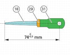
If the pushrod (18), clip (30) and fork (31) assembly has been dismantled, reassemble it by screwing the nut (29) onto the rod (18) and then screw the rod into the fork (31) to obtain the measurement indicated in the figure.
Block the rod and tighten to a torque of 7.5 Nm +/- 10% (sect. 3 - 3, Frame torque settings) the nut (29) on the fork (31).
Fit the pushrod assembly (18) on the lever (6) fixing it with the quick-release fastener (30).

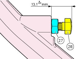
Check that the adjuster screw (27) and nut (28) are positioned at the distance apart shown.
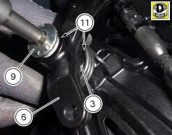
Apply specific grease to the non-threaded surface of the pin (9).
Fit the first o-ring (11) in the pin (9).
Insert the pin (9) on the brake lever (6), apply the recommended grease to the seat of the second o-ring (11) of the lever (6) and place the other o-ring (11) and the washer (3).
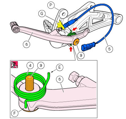
Fit the spring (4) on the rear brake lever (6) observing the orientation shown.
Apply the recommended threadlocker to the threaded side of the pin (9).
Fit the brake lever (6) on the footrest bracket (p) inserting the pin (9).
Note
On refitting, place the end (e) of the spring against the suitable rib of the bracket (p), making sure the other end (f) of the spring remains in place as shown.
Fit the rear stop sensor wire (5) tightening it manually onto bracket (g) and then to a torque of 10 nm +/- 10% (sect. 3 - 3, Frame torque settings).
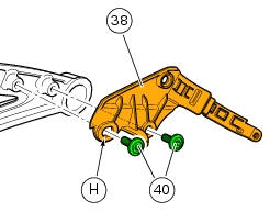
If removed, refit the master cylinder (38) on the bracket by starting the screws (40).
Note
Start the screw (40) first; this is the screw that sits in the slot (h).
Tighten the screws (40) to a torque of 4 nm +/- 10% (sect. 3 - 3, Frame torque settings).
Reconnect the hose (7), locating the sealing washers (23) on both sides of the hose end fitting, and secure it with the special screw (22).
Tighten the special screw (22) to a torque of 23 nm +/- 10% (sect. 3 - 3, Frame torque settings).
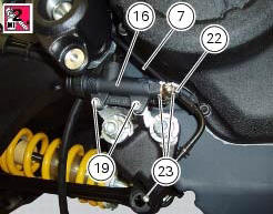
Note
Pay special attention to the pipes (7) and (21) orientation on the rear brake master cylinder (16).

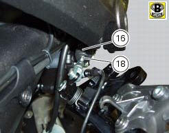
Insert the rod (18) inside the pump (16), after applying the recommended grease.
 Disassembly of the rear brake control
The brake master cylinder is supplied only as a complete unit; internal
components cannot be replaced.
To disassemble the master cylinder's outer parts, follow the indications given
in the expl ...
 Removal of the rear brake calliper
Important
The brake manufacturer advises against any servicing of the internal
components of brake callipers or the master cylinder.
Incorrect overhaul of these critical safety components can en ...
Other materials:
Footrest brackets
Rubber footrest
Right front footrest
Pin
Spring
Circlip
Right footrest bracket
Screw
Washer
O-ring
Bush
Rubber pad
Right rear footrest
Pin
Ball
Spring
Plate
Screw
Vibration damper mount
Special screw
Front lh footrest
Left footrest bracket
Left rear f ...
Legal rights
This warranty gives you specific legal rights, and you may
also have other rights which vary from state to state.
This warranty is in addition to the ducati limited
motorcycle warranty.
Additional information
Any replacement part that is equivalent in performance and
durability may be used in ...
Refitting the radiator
The reassembly procedure is the same for both radiators.
Check for the nuts with clips (8).
Refit the rh radiator (13) on the frame and tighten the screws (4) and (5)
with the spacers (6) to a torque of 10 nm
+/-10% (sect. 3 - 3, Frame torque settings).
Connect the connections of ...