
Ducati Diavel Service Manual: Refitting the rear footrests
Note
The refitting of the rear footrests is described for the right side but it is the same for both.
If previously removed, refit the rubber footrest (11) on the rear rh footrest (6), by pushing it until pad (b) engages in the other side.
Note
The rubber footrest (11) side featuring the least width must be faced to the outer side of the footrest (12).
Apply recommended grease to the seats (g) of the o-rings and in area (h) on the rear rh footrest (12).
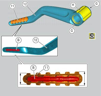
Place o-rings (9) in the relevant seats of the footrest (12).
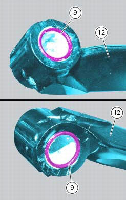
Position footrest (12) as shown, on the rear subframe rh bracket; make sure that the previously fitted o-rings do not come out of the relevant seats on the footrest (12).
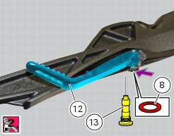
Fit washer (8) between footrest (12) and the rear subframe rh bracket.
Fix the footrest (12) by starting the pin (13) smeared with specified threadlocker.
Tighten the pin (13) to a torque of 30 nm +/- 10% (sect. 3 - 3, Frame torque settings).
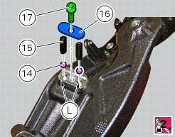
If previously removed, apply recommended grease into the holes (l) and insert balls (14) and springs (15) into the relevant holes of the rear subframe rh bracket.
Apply prescribed threadlocker on the screw thread (17).
Fit the cap (16) and tighten the screw (17) to a torque of 10 nm +/- 10% (sect. 3 - 3, Frame torque settings)
 Removing of the rear footrests
The removal of the rear footrests is described for the right side but it is
the same for both.
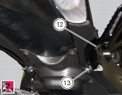
Undo the pin (13) and remove the rh rear footrest (12) from the frame.
Recover washer (8) and the ...
 Stands
Side stand
Side stand switch
Screw
Plate
Screw
Inner spring
Outer spring
Nut
Rotation pivot
Screw
Screw
Screw
Nut
Clearance adjuster
Spare parts catalogue
Diavel a ...
Other materials:
Disassembly of the gearchange mechanism
Refer to the exploded view at the beginning of this section for indications
on disassembly and renewal of gearchange
components.
If the bushing (2) inside the pedal (1) needs replacing, grease the external
surface and drive the new bushing into place
using a press. The bushing must be seate ...
Pre-ride checks
Warning
failure to carry out these checks before riding, may
lead to motorcycle damage and injury to rider and passenger.
Before riding, perform a thorough check-up on your bike as
follows:
Fuel level in the tank
Check the fuel level in the tank. Fill tank if needed (page 140).
Engine oil le ...
Refitting the camshafts
If the stud bolts (2) were removed, apply the recommended threadlocker to the
short end of the stud bolts (2), i.E. The
end that is to be screwed into the cylinder head. Tighten the stud bolts (2) to
a torque of 10 nm (min. 9 Nm - max. 11
Nm) (sect. 3 - 3, Engine torque settings).
Check t ...