
Ducati Diavel Service Manual: Refitting the rear suspension
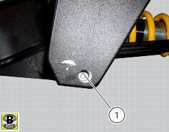
Lubricate the thread and underside of the special screw (1).
Insert the lower side of the shock absorber into the swingarm and insert the screw (1).
Tighten the screw (1) to a torque of 45 nm +/- 5% (sect. 3 - 3, Frame torque settings).
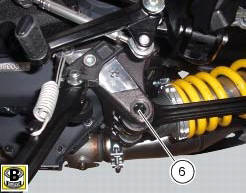
Lubricate bushes (5) and (6) with recommended grease.
Position the upper part of the shock absorber assembly on the supporting plate and fit bush (6) on the lh side of the vehicle, and bush (5) on the right side.
Tighten the bush (5) to a torque of 45 nm +/- 10% (sect. 3- 3, Frame torque settings) while holding the bush (6).

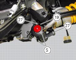
Refit the tank assembly (s) of the shock absorber on support (19) and tighten the screws (27) to a torque of 10 nm +/- 10% (sect. 3 - 3, Frame torque settings).
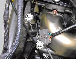
Reposition the assembly (34) on the frame and tighten the screws (22) to a torque of 10 nm +/- 10% (sect. 3 - 3, Frame torque settings).
 Reassembly of rear shock absorber - rocker arm - linkage assembly
Once the needle roller bearings (9) have been removed from the rocker arm
(18), upon reassembly fit a new needle roller
bearing (9) on drift part no. 88713.1071 And lubricate with recommended greas ...
 Removal of the shock absorber support
Remove the rear brake master cylinder (sect. 7 - 4, Removing of the rear
brake control).
Remove the rear shock absorber (see removal of the rear shock absorber of this
section).
Loosen the s ...
Other materials:
The battery charging circuit and power distribution
On the diavel, the +15v (key on power) voltage does not come from a
conventional ignition key, but from pin 30 of the
hands free relay. This relay is switched to closed state by the hands free unit
when the latter enables power on for the
ignition and engine. The hands free relay receives +30v ...
Headlight control
This function allows you to reduce current consumption from
the battery, by automatically managing headlight switchingoff.
At key-on, the high beam and low beam lights are off.
When the engine is started, the low beam lights turn on
automatically; from this moment, "normal" operati ...
Indicator cons. Avg - average fuel consumption
This function indicates the "average" fuel consumption.
The calculation is made considering the quantity of fuel used and the km
travelled since the last trip 1 reset. When trip 1
is reset, the value is set to zero and the first available value is shown on the
display 10 seconds after the re ...