
Ducati Diavel Service Manual: Refitting the rear wheel eccentric hub and rear wheel shaft
Refitting is the reverse of removal, with attention to the following points.
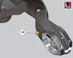
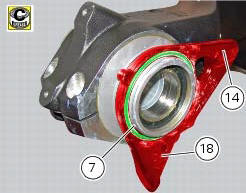
If the calliper bracket locating pin (14) was removed, apply the recommended threadlocker on reassembly.
Tighten the pin (14) to the torque of 33 nm +/- 5% (sect. 3 - 3, Frame torque settings).
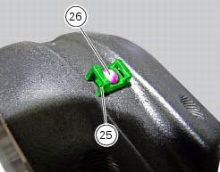
If previously removed, refit the cable grommet (25) as shown in the figure and tighten the screw (26) to a torque of 1 nm +/- 10% (sect. 3 - 3, Frame torque settings).
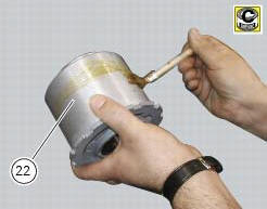
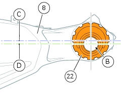
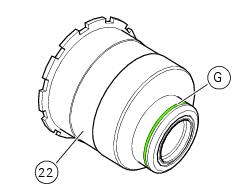
Before refitting apply some recommended grease to the eccentric hub (22) external surface.
Insert the hub (22) fully home on the swingarm (8).
Note
During this operation force the hub seat open on the swingarm enough to fit the hub (22).
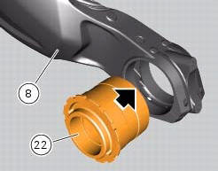
Check that the eccentric hub (22) with respect the swing arm (8) features the horizontal axis (d) of the hub bore (b) under the horizontal axis (c) of the hub seat.
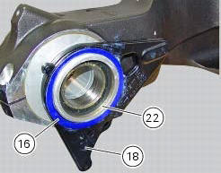
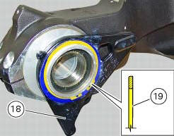
Apply grease on rings (17) and place them in their seat of the plate (18). Fit the washer (16) on the eccentric hub (22).
Place the plate (18) on the swingarm: the pin (14) must match with the blind slot (t) on the plate (18).
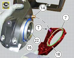
Refit the other washer (16) on the eccentric hub (22).
Block the plate (18) after installing circlip (19) in its groove (g) on hub (22), and setting it with its square edge outward.
Note
After this operation visually check that the circlip is perfectly inserted in the groove (g).
Apply an even coating of the recommended grease in the areas (a) of the axle (31).
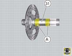
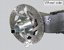
Insert the rear wheel shaft (31) in the hub (22).
Ensure the stub axle (31) is seated in the hub.
Fit the inner ring (21) on the wheel shaft (31).
Insert the inner ring (21) in the hub.
Apply the recommended grease to the screws (a) and tighten to the torque of 35 nm+/-5%(sect. 3 - 3, Frame torque settings) following the sequence 1-2-1.

Set the chain tension as described in sect. 4 - 3, "Adjusting the chain tension".
 Removal of the rear wheel eccentric hub and rear wheel shaft
Before removing the eccentric hub, you must first remove the parts listed
below.
Slacken off the screws (34).
Remove the spacer (20) and the inner ring (21) on the chain side and remove the ...
 Removal of the swingarm
Before removing the parts in question, you must first carry out the following
operations:
Remove the rear wheel eccentric hub as described in chapter "removal of the
rear wheel eccentric hub ...
Other materials:
Refitting the timing belts
Rotate the pulleys on the timing belt driveshaft until the timing mark on the
outer roller is aligned with the mark on the
clutch-side crankcase cover.
In this condition, the horizontal cylinder piston will be at top dead centre.
Install in the alternator cover seat the tool code 88713.20 ...
Steering angle adjustment
Loosen the nuts (17) and adjuster screws (16) on both sides of the bottom
yoke.
Use a 6 to 6.5 Mm spacer (a) fitted to the fork outer tube, or use a gauge.
Turn the front forks to the right until the spacer (a) is seated against the
frame top tube.
Tighten the adjuster screw (16) to ...
Changing bulbs
Changing the headlight bulbs
Before replacing a burnt out light bulb, ensure that the replacement bulb has
the same voltage and power rating as
specified for the lighting device in question (sect. 3 - 1.1, Lights/instrument
panel).
Warning
The halogen light bulbs in the headlight become hot ...