
Ducati Diavel Service Manual: Refitting the side stand
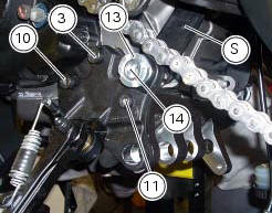
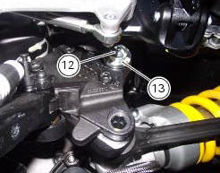
Place the stand plate on the rear shock absorber support; bring adjuster (14) in line with bracket (s) and start the screw (12) in the nut behind the bracket (s).
Insert the screws (11), (3) and (10) fully home in this order, but do not tighten.
Loosen the screw (12) with the relative nut, tighten the adjuster (14) to a torque of 0.6 Nm +/- 10% (sect. 3 - 3, Frame torque settings) and tighten the screw (12) to a torque of 2 nm +/- 10% (sect. 3 - 3, Frame torque settings) while holding the nut.
Locate service tool no. 88713.3166 On the ring nut (13) and fit the torque wrench to the tool. While holding the adjuster (14), tighten the ring nut (13) to a torque of 100 nm +/- 5% (sect. 3 - 3, Frame torque settings).
Tighten screws (11), (3) and (10) in this order to a torque of 44 nm +/- 10% (sect. 3 - 3, Frame torque settings).
Finally, tighten the screw (12) to a torque of 45 nm +/- 10% (sect. 3 - 3, Frame torque settings) while holding the nut.
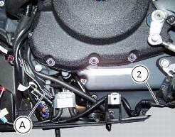
Connect connector (a) of the side stand switch to the main wiring harness.
To place the stand switch wiring refer to the table (sect. 6 - 1, Routing of wiring on frame).
 Removing of the side stand
Disconnect connector (a) of the stand switch (2) from the main wiring.
Loosen the screws (3), (10), (11) and (12) securing the stand bracket (4) to
the engine and remove the complete side
...
 Frame inspection
Frame
Rh subframe
Lh subframe
Grub screw
Nut
Special screw
Rubber pad
Nut
Special screw
Screw
Left-hand bracket
Hose clip
Hose clip
Right-hand bracket
Special screw
...
Other materials:
Disassembly of rear shock absorber - rocker arm - linkage assembly
Undo the screw (15) and remove the rear shock absorber (11) from the rocker
arm (18).
Undo
Undo the screw (14) and the nut (21) and remove the linkages (10) and (12)
from the rocker arm (18).
The rocker arm movement is obtained by needle roller bearings (9) rotating on
a spacer (1 ...
Menu 2 on/off function
This function turns off and back on the menu 2.
If menu 2 is disabled, the functions for average fuel
consumption (cons.Avg), instantaneous fuel consumption
(cons.), Average speed (speed avg), trip time (trip time)
and air temperature (air) will no longer be displayed in the
"main screen ...
Refitting the crankshaft/connecting rod assembly
Install the connecting rod assembly (6) and (2) in the crankcase, carry out
the shimming and crankcase half reassembly
procedure as described in sect. 9 - 9.2, Reassembly of the crankcase halves.
Important
Make sure that the connecting rods (2) are correctly positioned in the
cylinders. Incor ...