
Ducati Diavel Service Manual: Refitting the steering head components
Important
The steering tube bearings (6) are identical but in no case may their components be swapped around during reassembly.
Clean all contact surfaces and lubricate with the recommended grease.
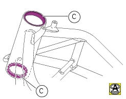
To fit the external rings (c) of the bearings (6) to the steering tube, use the tool with part no. 88713.1062 And proceed as follows:
- Heat the steering head to 150 C;
- Fit the outer races (c) in their seats on the steering head;
- Fit the fixed bush (g, with threaded hole) of the tool into the lower race;
- Fit the other movable bush (h) into the upper end of the tool and drive it fully home against the upper bearing race;
- Tighten the nut (l) and use a wrench to seat the outer races (c) fully in the steering head;
- Leave the tool assembled until the steering head has cooled down to ensure that bearings are properly seated.
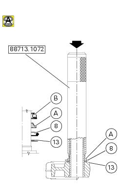
Insert the washer (13), seal (8) (with the rim facing upwards) and inner ring (l) of bottom bearing (6) onto the steering shaft after heating it for about 10 minutes to 120C.
Insert drift part no. 88713.1072 Onto steering shaft. Push the inner ring (l) on the sealing ring (8), manually pushing for at least 10-15 seconds.
Lubricate the inner bearing race (l) with the recommended grease.
Fit the ball race (m) on the steering shaft with the smaller diameter of the cage facing upwards and grease the ball race.
Insert the steering shaft in steering head and push it in until it is axially seated.
Fit the bottom yoke assembly to frame.
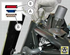
Grease the ball race (b) and fit it to frame top outer race (c).
Fit the inner ring (a) of the upper bearing (6) to the steering head, with the larger diameter side of the race facing upwards.
Install the sealing ring (8) with the flat side facing upwards.
Grease the nut (12).
Tighten the steering shaft nut (12) by hand until it seats against the sealing ring (8).
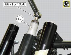
Fit service bush no. 88713.1058 To the steering shaft nut (12) and fit the torque wrench to the bush.
Tighten the adjuster ring nut (12) to a torque of 30 nm +/-5% (sect. 3 - 3, Frame torque settings).
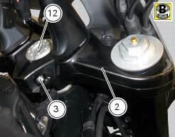
Fit the steering head (2) on the steering head nut (12), aligning the fork leg bores with the corresponding bores on the bottom yoke. Relocate the fork legs as described in section 7 - 10.1, Refitting the front forks.
Grease the screw (3).
Tighten the screw (3) on the steering head to a torque of 24 nm +/-5% (sect. 3 - 3, Frame torque settings).
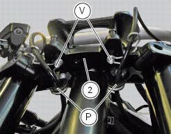
Refit the cable grommet (p) on the steering head and tightening the screws (v) to a torque of 8 nm +/-10% (sect. 3 - 3, Frame torque settings).
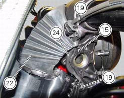
Mount the front support (24) on the right support (23) and the front splashguard (22) on the left support (21), inserting the splashguard pins (p) into the holes in the supports.
Note
For the supports (21), (23) and (24) to be installed correctly, the pins (p) must be fully out at the side opposite to insertion site.
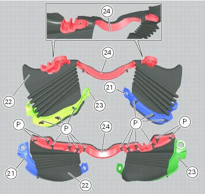
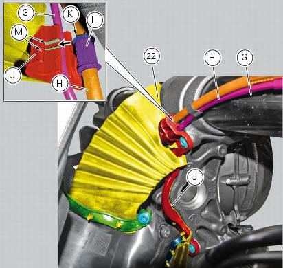
Position the front speed cable (g) and the brake hose (h) in the suitable seats provided by the front support (j) of the splashguard (22) as shown.
Note
To position the brake hose (h) correctly, insert collar (k) of rubber (l) into the guides (m) on the front support (j).
Place the front support (24) of the splashguard (22) on the bottom yoke (15) by tightening the screws (19) to a torque of 4 nm +/- 10% (sect. 3 - 3, Frame torque settings).
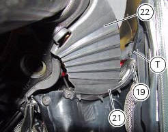
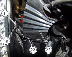
Fix supports (21) and (23) of the splashguard (22) to the air conveyors (t) by tightening the screws (19) to a torque of 4 nm +/- 10% (sect. 3 - 3, Frame torque settings).
Operations
 Removal of the steering head components
Note
All parts fitted to the top and bottom yokes, including the wiring and
control cables, can remain on the motorcycle
provided they do not hinder the following operations.
Loosen the screw ...
 Rear shock absorber assembly
Special screw
Screw
Nut
Grub screw
Bush (right)
Bush (left)
Screw
Sealing ring
Roller bearing
Linkage (left)
Shock absorber (rear)
Linkage (right)
Spacer
Special screw ...
Other materials:
Removal of the crankshaft/connecting rods assembly
After separating the crankcase halves, withdraw the crankshaft (6) complete
with connecting rods (2).
...
Electrical power for lighting and signalling devices
The front and rear running lights consist of led units with light conduits.
As a result, the light source is not visible as the
light is diffused through the surface of the light conduit.
These two images illustrate the front and rear running lights with light
conduits.
The figure ...
Transmission
Wet clutch controlled by the lever on left-hand side of the
handlebar.
Transmission from engine to gearbox primary shaft via spur
gears.
Front chain sprocket/clutch gearwheel ratio:
33/61
6-speed gearbox with constant mesh gears, gear change
pedal on left side of motorcycle.
Gearbox ou ...