
Ducati Diavel Service Manual: Refitting the tail light
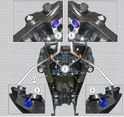
Fit the spacers with collar (3) into the rear vibration dampers (2) located on the gloves compartment (23).
Note
Two spacers (3) must be inserted inside and outside on the right side and two spacers (3) must be inserted inside and outside on the left side.
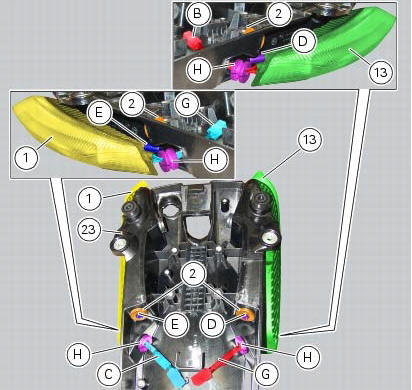
Insert the split vibration damper (h) on the wiring (g) of the left optical unit (13) and the split vibration damper (h) on the wiring (c) of the right optical unit (1).
Note
The usa version uses red optical units (13) and (1).
Fit the left optical unit (13) and the right optical unit (1) on the compartment (23), inserting their pins (d) and (e) into the vibration dampers (2).
Fit the split vibration dampers (h) into the corresponding holes of the compartment (23).
Fit the washers (14) on the screws (4).
Fix the optical units (13) and (1) to the compartment (23) starting the screws (14).
Note
The screws (14) must be inserted into the internal spacers (3) fitted previously.
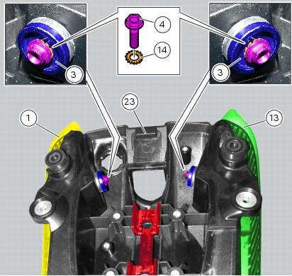
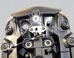
Tighten the screws (4) to a torque of 6 nm +/- 10% (sect. 3 - 3, Frame torque settings).
 Removal of the tail light
Disconnect the connectors (a) and (b) of the tail lights (1) and (13).
Loosen the screws (4) and slide the tail lights (1) and (13) to the rear side;
recover the four spacers (3) and the wash ...

Other materials:
Clutch lever button
Introduction
The clutch button is located on the clutch lever. Together with the signal
from the side stand button and the neutral signal
generated by the gear sensor (transmitted to the engine control unit over the
can line), the clutch lever position signal is
used to enable or disable engi ...
Overhauling the front forks
Note
It is advisable to loosen the top cap (14) when the fork is still fitted
to the motorcycle.
Note
The specific tools for the revision of the fork, are described in sect. 3
- 4, Specific tools for the frame.
Loosen the spring preload adjuster before unscrewing the plug (14).
Unscrew th ...
Programming/reprogramming keys
The dds diagnosis instrument is required in order to programme/reprogramme
the keys. The key programming procedure
is launched from this instrument.
To start the key programming/reprogramming procedure it is necessary to have at
least one of the keys that start the
vehicle available (i.E. I ...