
Ducati Diavel Service Manual: Refitting the water pump
Clean the seat on the cover, any parts you intend to reuse, and the impeller shaft. Then refit as follows.
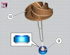
Fit on the impeller (10) shaft the mechanical seal (9) as indicated in the figure.
Apply specified lubricant to facilitate the insertion.
Bring the mechanical seal fully home on the impeller.
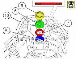
Grease the seat (a) of the bearings for the impeller on the generator cover (12).
Insert spacer (7) fully home into the generator cover by orienting it so that the round edge is faced down.
Fit bearing (6) completely into the spacer.
Fit bearing (5) completely on the bearing (6).
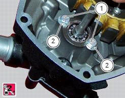
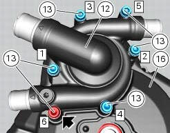
Fit the washers (2) on the screws (1).
Orient the washers so that the knurled side is faced to the screw head.
Apply recommended threadlocker to the screws.
Fit the two screws (1) and tighten them to a torque of 10 nm (min. 9 Nm - max. 11 Nm) (sect. 3 - 3, Engine torque Settings).
Turn the cover upside down.
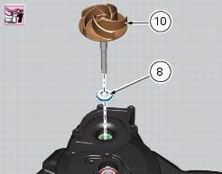
Introduce the counterface (8) completely into the generator cover.
The counterface must be oriented so that the white side is faced upwards.
Apply specified lubricant to facilitate the counterface insertion.
Clean the counterface from exceeding lubricant.
Install the water pump impeller (10) and bring completely against the counterface.
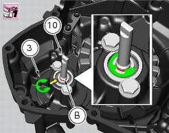
Use the special tools to install the snap ring (3) into the proper groove (b), on the impeller (10) shaft, as shown in figure.
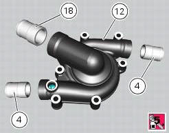
If previously removed, apply specified threadlocker on the threads of the water pump delivery unions (4).
Fit the unions on the water pump cover (12) and tighten them to a torque of 25 nm (min. 23 Nm - max. 27 Nm) (sect. 3 - 3, Engine torque settings).
Apply recommended threadlocker on the thread of the water pump intake union (18).
Fit the union on the water pump cover (12) and tighten it to a torque of 25 nm (min. 23 Nm - max. 27 Nm) (sect. 3 - 3, Engine torque settings).
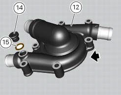
If previously removed, insert washer (14) into the plug of the water pump cover (15).
Fit the plug on the water pump cover (12) and tighten it to a torque of 20 nm (min. 18 Nm - max. 22 Nm) (sect. 3 - 3, Engine torque settings).
Clean the mating surfaces thoroughly on the pump cover and on the alternator-side crankcase cover.
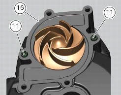
If previously removed, install the two centring bushes (11) completely into the generator cover.
Apply a bead of fluid gasket on the generator cover (16).
Insert the fixing screws (13) and (18) of the cover.
Tighten the screws (13) to a torque of 10 nm (min. 9 Nm - max. 11 Nm) (sect. 3 - 3, Engine torque settings).
Tighten the screws (13) to a torque of 13.5 Nm (min. 12.5 Nm - max. 14.5 Nm) (sect. 3 - 3, Engine torque settings) following the indicated sequence.
Refit the components removed in the procedure.
![]()
 Removal of the water pump
Note
For clarity, the figures show the engine removed from the frame.
Loosen and remove the water pump cover (12) fixing screws (13) to the
generator cover (16).
Remove the water pump cover ...

Other materials:
The battery charging circuit and power distribution
On the diavel, the +15v (key on power) voltage does not come from a
conventional ignition key, but from pin 30 of the
hands free relay. This relay is switched to closed state by the hands free unit
when the latter enables power on for the
ignition and engine. The hands free relay receives +30v ...
Lubricating cables and joints
Check the outer sheath of the throttle control and cold start
lever cables for damage at regular intervals. The outer plastic
cover should not be flattened or cracked. Operate the
controls to make sure the inner cables slide smoothly inside
the outer sheath: if you feel any friction or catching, ...
Removal of the gearbox assembly
Withdraw the selector fork shafts (30).
Move the forks (28) and (29) to disengage them from the slots in the selector
drum (14).
Withdraw the selector drum (16) taking care not to lose shims (31) and (27)
mounted on the shaft. Note that the
positions of the shims must not be inverte ...