
Ducati Diavel Service Manual: Removal of the clutch master cylinder assembly
Warning
The clutch master cylinder manufacturer advises against servicing of the clutch master cylinder (1) due to the safetycritical nature of this component. Incorrect overhaul of this component could endanger rider safety.
Maintenance operations of the master cylinder are limited to replacing the following parts: control lever, reservoir unit, and master cylinder fasteners.
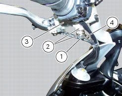
Loosen the special screw (1) by collecting the seals (2), to release the clutch master cylinder assembly (3) from the clutch control pipe (4).
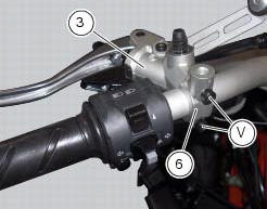
Undo the fixing screws (v) of the mounting u-bolt (6) and then remove the clutch master cylinder unit (3) from the handlebar.
Refer to the exploded view at the beginning of this section for indications on disassembly and replacement of the master cylinder components.
 Hydraulic clutch control
Special screw
Sealing washer
Clutch master cylinder
Clutch hydraulic pipe (metal braid)
Screw
Spare stand
Washer
Microswitch
Pin
Bleed valve
Screw
Roller
O-ring
Clutch ...
 Refitting the clutch master cylinder assembly
Insert the clutch master cylinder assembly (3) and the clamp (6) on the left
handlebar, so that the top mating faces
match the mark (z) on the handlebar as shown.
Couple terminal (6) to th ...
Other materials:
Reassembly of the control unit
Insert the control unit (4) into the protecting sheath (5) and position it on
the airbox.
Position the relay supporting bracket (2) by starting and tightening the
screws (1) to a torque of 6 nm +/- 10% (sect. 3 -
3, Frame torque settings), and connect the control unit connectors (3).
...
Flywheel - alternator
Screw
Alternator stator
Plug
Sealing ring
O-ring
Cover
Screw
Aluminium gasket
Screw
Bracket
Locating bush
Screw
generator cover
Flange
Flanged nut
Plane washer
Flywheel
Washer
Inner ring
Needle roller bearing
Electric starter driven gear
Starter clutc ...
Bleeding of the abs hydraulic system
If some "sponginess" is detected on the brake control, due to air bubbles in
the system, bleed the system, as indicated in
sect. 4 - 3, Changing the brake fluid.
Before bleeding a brake pump, move back the calliper pistons, as indicated in
(sect. 4 - 3, Changing the brake fluid) to Drain in ...