
Ducati Diavel Service Manual: Removal of the clutch transmission unit
Warning
The manufacturer of the clutch transmission unit (15) advises against servicing of its internal parts due to the safetycritical nature of this component.
Incorrect overhaul of these critical safety components can endanger rider and passenger safety.
The only components that should be renewed are the complete clutch transmission unit, the bleed valve, the seals and the complete clutch pushrod assembly.
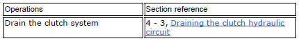
Undo the screws (11) and slide out the clutch slave cylinder (r).
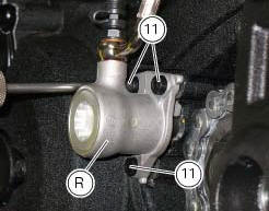
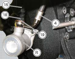
Remove the dust gaiter (16) and the bleed valve (17) and unscrew the screw (18), taking care to recover the gaskets (19): the unit (r) is now disconnected from the pipe (4).
Push in the piston to force out all the fluid from inside the cap.
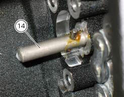
At this point, it is possible to slide also the clutch gear rod (14).
 Refitting the clutch master cylinder assembly
Insert the clutch master cylinder assembly (3) and the clamp (6) on the left
handlebar, so that the top mating faces
match the mark (z) on the handlebar as shown.
Couple terminal (6) to th ...
 Refitting the clutch transmission unit
Position pipe (4) on the clutch slave cylinder (r).
Position the two seals (19) and tighten the screw (18) to a torque of 23 nm +/-
10% (sect. 3 - 3, Frame torque settings).
Refit the bleed valv ...
Other materials:
Warranty
In your own interest, and in order to guarantee product
reliability, you are strongly advised to refer to a ducati dealer
or authorised service centre for servicing that requires any
particular technical expertise.
Our highly skilled staff have the tools required to perform any
servicing job ...
Abs fault indicator not working
Fault codes
Dds: displays a fault code described in the description of the abs system.
Dashboard: no fault code displayed.
Wiring diagram
Checks
The abs fault indicator indicates the occurrence of one or more faults in the
antilock brake system, or if the system itself
has been disable ...
Shimming the shafts
Before assembling the crankcase halves, calculate the shims required to
obtain the correct end float of the crankshaft and
gearbox shafts.
To determine the correct shim thickness proceed as follows.
Shimming the crankshaft
After having installed the new main bearings (with bushing (a) or ...