Ducati Diavel Service Manual: Removal of the control unit
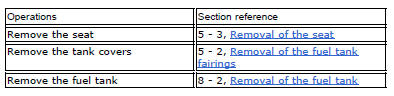
Loosen the screws (1) and remove the relay supporting bracket (2), disconnect the connectors (3) and remove the control unit (4) from the vehicle.
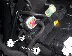
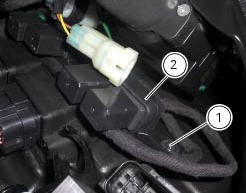
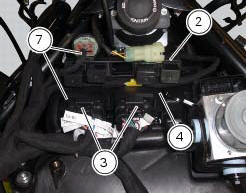
 Layout of engine control system and other components
Injection relay
Etv relay (throttle valve operating engine)
Fan radiator relay
Hands free relay
Ecu
...
 Reassembly of the control unit
Insert the control unit (4) into the protecting sheath (5) and position it on
the airbox.
Position the relay supporting bracket (2) by starting and tightening the
screws (1) to a torque of 6 ...
Other materials:
Inputs and outputs of engine control unit and connection to can network
The diagram illustrates the inputs and outputs for the engine control unit.
The signals from the brake buttons, the exhaust
by-pass valve command signal and the gear sensor signal are transmitted over the
can line.
1I emergency engine cutout switch
2I start button
4I side stand button
6 ...
Engine
Twin cylinder, four-stroke, 90 "l" type, longitudinal, with
deep sump die-cast crankcase.
Bore, mm: 106
Stroke, mm:
67.9
Total displacement, cu. Cm:
1198
Compression ratio:
11.5В±0.5:1
Max power at crankshaft (95/1/ec), kw/hp:
119 kw/162 hp at 9,500 rpm
Max torque at crankshaf ...
Fuel system circuit
The fuel system circuit consists of:
An electric pump, driven by the injection relay, which is in turn
controlled by the ecu (engine control unit)
A fuel filter
A pressure regulator
Two injectors (one per cylinder, located downstream of throttle valve)
The plastic mounting shown in t ...