
Ducati Diavel Service Manual: Removal of the cylinder/piston assembly
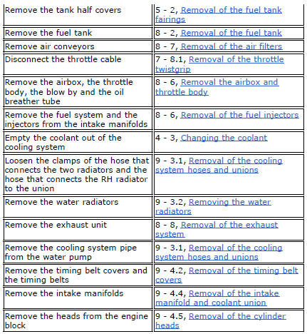
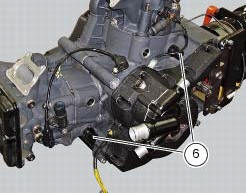
Loosen the clamps (7) and remove the hoses (8) and (9) from the cylinder barrels (10) and from the alternator-side crankcase cover.
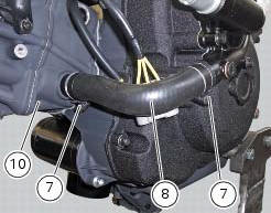
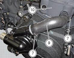
If damaged, unscrew the unions (6).
Note
The following procedure is described with the engine removed from the frame and the cylinder head removed from the engine (sect. 9 - 4.5, Removal of the cylinder heads).
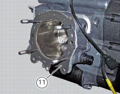
Remove the gasket (11) from the horizontal thermal unit.
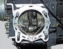
Remove the bushes (12).
Use the tool 88765.1523 To bring the piston of the horizontal cylinder near the tdc.

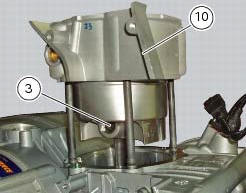
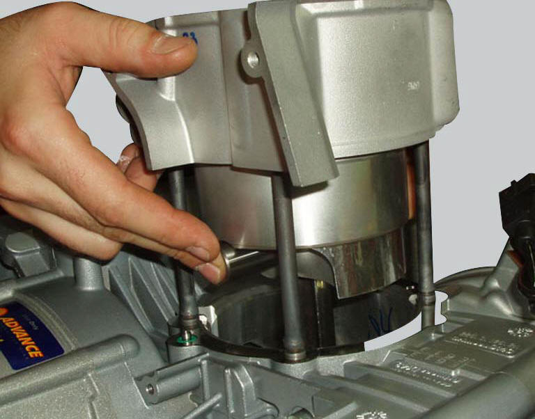
Carefully lift the cylinder barrel (10) off the crankcase, keeping it vertical.
If necessary, rock the cylinder slightly using both hands or tap its base gently with a rubber mallet. Continue to lift the cylinder until you can access the gudgeon pin (3).
Note
For better sealing the piston ring gaps should be positioned at 180 intervals.
Since insertion of piston in the barrel is a difficult operation to perform at the time of reassembly, remove the piston together with the barrel as described below.
Stuff the crankcase opening with a rag or soft paper to prevent foreign material from falling in.
Remove the circlip (2) from the gudgeon pin (3) on the clutch side.
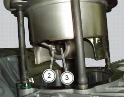
Working from the opposite side, drive out the gudgeon pin sufficiently to release the connecting rod.
Lift the barrel-piston assembly clear of the crankcase studs. If work is to be carried out on the piston, carefully withdraw it from the cylinder.
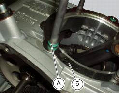
Remove the four o-rings (a) located on the crankcase studs between the barrel and the base gasket (5).
To remove the vertical barrel-piston assembly, bring the vertical piston to tdc and proceed as for removal of the horizontal cylinder barrel.
Important
Mark the pistons to show from which cylinder they were removed: v= vertical - h= horizontal.
 Cylinder/piston assemblies
Piston
Gudgeon pin circlip
Gudgeon pin
Set of piston rings
Cylinder-crankcase gasket
Water pump outlet union
Hose clip
Horizontal cylinder coolant inlet hose
Vertical cylinder c ...
 Overhaul of the cylinder barrel/piston components
Overhauling the cylinder
Check that the walls of the cylinder bore are perfectly smooth. Measure the
cylinder bore diameter at 50 mm from the top
face and determine the size class to which it belo ...
Other materials:
Refitting the silencer
Position the silencer guard (41) and fix it by starting the screws (40).
Tighten the screws (40) to a torque of 8 nm +/- 10% (sect. 3 - 3, Frame torque
settings).
Insert the silencer (4) into the central exhaust pipe (26), and fix it to the
vehicle by starting the screw (1).
Hold the ...
General safety rules
Carbon monoxide
When a maintenance operation must be performed with the engine running, maker
sure that the working area is wellventilated.
Never run the engine in an enclosed space.
Warning
Exhaust fumes contain carbon monoxide, which is a poisonous gas that
can cause unconsciousness or e ...
Front and rear mudguard
Front mudguard
Washer
Rivet
Clip
Screw
Spacer
Screw
Rear mudguard
Screw
Spare parts catalogue
Diavel abs rear swingarm
Diavel abs belly fairing
Diavel carbon
abs
rear swingarm
Diavel carbon
abs
belly fairing
Important
Bold reference numbers in this section identif ...