
Ducati Diavel Service Manual: Removal of the engine
In order to remove engine you must first remove a series of other components from the motorcycle.
Most of these removal procedures are described in the relative sections of this manual.
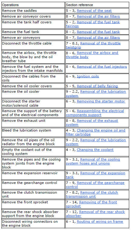
The following flow chart illustrates the logical sequence in which the parts are to be removed from the motorcycle and a reference to the section where the removal procedure is described.
This section describes only the operations to be carried out after having removed all the parts listed in the flow chart.
Place a stand beneath the engine to support it during removal from the frame.
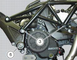
Loosen the nuts (3) on the right side of the frame, in correspondence to the engine upper supporting screws (1) and (4).
Block the special screw (6) of the swingarm shaft on the left side of the frame and at the same time undo the other special screw (6) on the right side.
Using the drift 88713.1074, Fully extract the swingarm shaft: from the lh side and recover the washer (7).
In this way the swingarm is not fixed to the engine any more, leave it connected to the frame.
Remove the upper supporting screws (1) and (4).
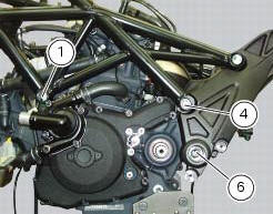
Withdraw the complete engine assembly from the frame by lowering it and pushing it forwards.
 Removal-refitting of the engine assembly
Screw
Special screw
Nut
Screw
Swingarm pivot
Special screw
Washer
Spare parts catalogue
Diavel abs frame
Diavel abs swingarm
Diavel carbon
abs
frame
Diavel carbon
abs
swi ...
 Refitting the engine
Refitting is the reverse of removal.
Important
Apply recommended grease and tighten the special screws (6) to a torque of
60 nm +/- 5% (sect. 3 - 3, Frame torque
settings).
Tighten the nuts (3) ...
Other materials:
Dtc (ducati traction control) setting function
This function allows you to customise the level of dtc
intervention (ducati traction control) or disable it for every
riding mode.
To access the function it is necessary to view the "setting" menu page 48, using
button (1, fig. 14) ?"" or (2, fig.
14) ?" " sele ...
Clutch cover
Clutch-side crankcase cover
Screw
Screw
Oil level sight glass
Screw
Plate
Bush
Sealing ring
Shim washer
Circlip
O-ring
Locating bush
O-ring
Plug
Sealing washer
Screw
Plug
Panel
Spare parts catalogue
Diavel abs clutch-side crankcase cover
Diavel carbon
a ...
Riding style function (riding style change)
This function changes the motorcycle riding style.
Each riding style is associated with a different intervention level of the
traction control (dtc - ducati traction control) and
different engine power and output.
To change the motorcycle riding mode, press the reset button once
(3) and th ...