
Ducati Diavel Service Manual: Removal of the evaporative emissions canister
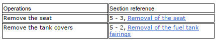
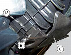
Loosen the screws (9) securing the plate (8) to the tank.
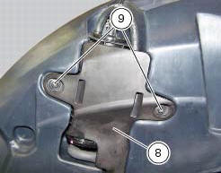
Slightly pull the plate (8) with the canister (13), remove the clamps (3) and (12) and connect hoses (7) and (14).
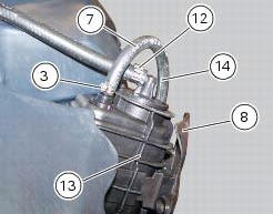
Release the retainers (b) of the plate (8) to remove it from the canister (13).
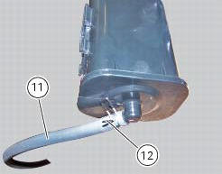
Disconnect the hose (11), removing the clamp (12).
Should it be necessary to replace one or more hoses, follow the procedure outlined in the paragraph "positioning the hoses / clamps and canister filter" of this section to determine the hose routing on the vehicle.
If removed, refit the rubber cover (10) on canister (13) using lubricant specific for rubber.
Fix cover (10) by positioning the tab (c) as indicated.
Introduce the spring (15) inside the hose (11) and reinsert the hose on fitting (d).
Note
The spring (15) must be introduced on the side of hose (11) which will be introduced inside the fitting (d).
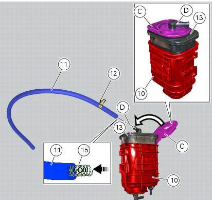
Fix the hose (11) with the clamp (12).
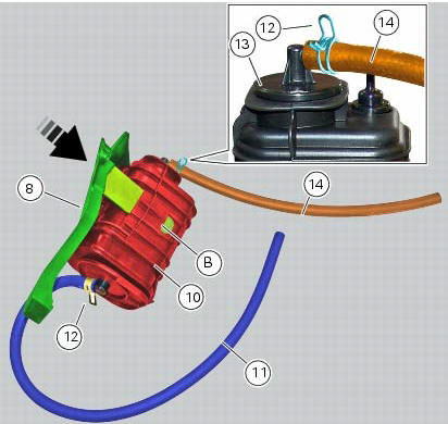
Fit the clamp (7) on the hose (14).
Mount the hose (14) on the upper fitting of the canister (13) and fix the hose (14) by means of the clamp (7).
Fit the plate (8) as indicated by inserting its lateral brackets (b) (on the right and left side) completely inside the slots on the rubber cover (10).
Note
In case of difficulties upon reassembly of the plate (8) we recommend to apply lubricant specific for rubber to the lateral brackets (b).
Place the plate (8) with the relevant canister on the tank and tighten the screws (9) to a torque of 4 nm +/- 10% (sect. 3 - 3, Frame torque settings).

 Evaporative emissions canister system (usa versions only)
Usa models are equipped with an additional system with an evaporative
emissions canister that prevents fuel fumes from
being discharged into the atmosphere.
The breather hose (4) is connected to t ...
 Refitting the evaporative emissions canister
To refit, carry out the removal operations in reverse order, making sure to
locate the hoses as shown in the figures at the
end of the chapter.
Positioning the hoses / clamps and canister filt ...
Other materials:
Refitting the external components
Fit the cap (39) on spring (38) until it engages.
Mount ball (40), spring (38) with cap (39), washer (37) and screw (36) on the
chain side half-casing by starting the
screw into hole (f).
Note
The spring (38), with cap (39), must be oriented as shown.
Tighten the screw fully home to a torqu ...
Removing the silencer
Loosen the clamp (38) that retains the silencer (4) to the complete exhaust
system.
While holding the nut (8), loosen the screw (1) and remove the silencer (4)
from the motorcycle.
Loosen the screws (40) and remove the silencer guard (41).
...
Checking and adjusting the valve clearances
Note
For clarity, the figures show the engine removed from the frame.
Move the piston of the cylinder being checked to tdc of the power stroke: in
this condition, all the valves are closed and
the timing shafts come in neutral position and, therefore, free to rotate; check
to the valve cl ...