
Ducati Diavel Service Manual: Removal of the exhaust system
Remove the silencer, as described in the paragraph "removing the silencer" of this section.
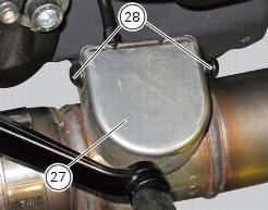
Loosen the screws (28) and remove the exhaust by-pass valve cover (27).
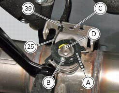
Turn the exhaust valve pulley (a) to facilitate the throttle cable (25) output.
Release the end fitting (b) of the cable (25) from the exhaust valve (d) and remove the circlip (39).
Release the control cable (25) from the plate (c).
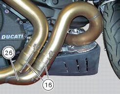
Remove the two retaining springs (16) and remove the central exhaust pipe (26).
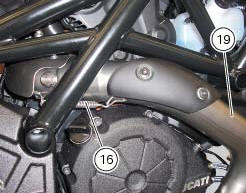
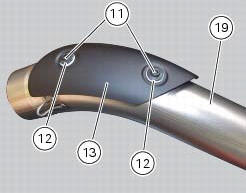
Remove the retaining spring (16) and the upper exhaust pipe (19).
Loosen the screws (11) and remove the heat guard (13) from the upper exhaust pipe (19); keep the spacers (12).
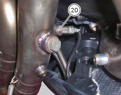
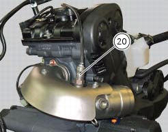
Undo and remove the horizontal cylinder lambda probe (20).
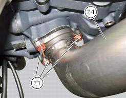
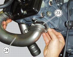
Undo and remove the three fixing nuts (21) and remove the horizontal manifold (24) with the gasket (23).
Undo and remove the vertical cylinder lambda probe (20).
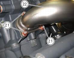
Undo and remove the three fixing nuts (21) and remove the manifold (22) with the gasket (23).
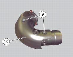
Unscrew the nuts (9) and remove the heat guard from the manifold (10).
 Removing the silencer
Loosen the clamp (38) that retains the silencer (4) to the complete exhaust
system.
While holding the nut (8), loosen the screw (1) and remove the silencer (4)
from the motorcycle.
Loose ...
 Refitting the exhaust system
Refit the heat guard on the manifold (10) by tightening the nuts (9) to a
torque of 10 nm +/- 10% (sect. 3 - 3, Frame
torque settings).
Position the vertical exhaust manifold (22) on the verti ...
Other materials:
Overhaul of the crankcase halves
Carefully examine the engine crankcase halves.
Check that the surfaces of the crankcase halves are perfectly flat using a
reference surface.
Check that the bearings (1) and (18), and the bushings (2) and (17) are in
optimum conditions. Note that the main
bearings must always be changed in p ...
Checking the camshafts and supports
Check the cam contact surfaces for scratches, grooves, steps and waving.
Worn cams are frequently the cause of poor timing, which leads to loss of engine
power.
Place the camshaft between two centres and check the run-out on the areas
indicated using two dial gauges.
Service limit: 0.1 ...
Reassembly of the clutch-side crankcase cover
Fit the plug (14) and the gasket (13). Fit the plug (17) and the gasket (15).
If the bush has been replaced, fully seat the new bush (7) in the slot in the
cover using a suitable drift and a press.
If the sealing ring (8) needs to be renewed, fit the new seal into the crankcase
cover, po ...