
Ducati Diavel Service Manual: Removal of the front brake system
Note
For the abs front braking system, also refer to sect. 7 - 5, Abs system operating information, sect. 7 - 6, System components, sect. 7 - 7, Abs components maintenance.
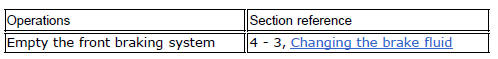
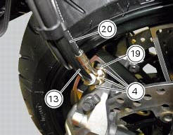
Undo the special screw (3), collect the sealing washers (4), and release the front brake master cylinder assembly (1) from the pipe.
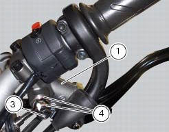
Tighten the screw (16) and slide the front brake pipe (13) from the bracket (17) on the yoke base.
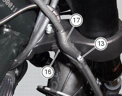
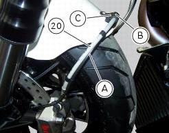
Loosen screw (c) to remove front brake hose (20) and the abs sensor cable (a) from hose clip (b).
Warning
While removing the front brake hose, if you damage the hose clip (b) you shall renew it (sect. 5 - 4, Removal of the front mudguard).
If hose is not fastened by hose clip (b), it might interfere with tyre under braking and provoke accidents.
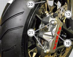
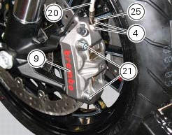
Unscrew the two fixing screws (21) of the left front brake calliper (9) to the fork leg.
Repeat the operation for the right brake calliper (18).
Undo the special screws (19) and (25) and collect, from both callipers, the sealing washers (4).
Detach the front brake callipers from the pipe (13) and (20).
Removal
 Maintenance operations
Warning
Brake fluid is corrosive and will damage paintwork. Avoid contact
with eyes and skin. In case of accidental contact, wash
the affected area with abundant running water and consult a doctor ...
 Removal of the brake discs
The front brake discs consist of an inner carrier, which is mounted to the
wheel, and an outer rotor. Both parts must be
changed together as a pair.
Remove the front wheel (sect. 7 - 1, Removal ...
Other materials:
Key-on/key-off using the red key on the handlebar with the passive key
A key-on can be performed by pressing the red button (6) on
the handlebar in the hands free on/off position and in
the presence of the passive key (4, fig. 77).
Note
The passive key (4, fig. 77) Has a range of a few cm,
therefore the key (4, fig. 77) Must be positioned near the
antenna (2). R ...
Lap registration function
This function describes the "lap" time registration.
If the function is activated (see "lap activation/deactivation description), the
lap time can be registered as follows:
pressing the flash headlight button (6) the first time starts the "lap timer"
for the first lap, and the dashboard show ...
Removing of the abs control unit
Drain the hydraulic fluid that is inside the front and rear braking system
tubes by disconnecting them from the master
cylinder and the calliper (sect. 4 -3, Changing the brake fluid).
Disconnect the connector (a) of the abs control unit (6).
Loosen the screws (16) that retain the abs ...