
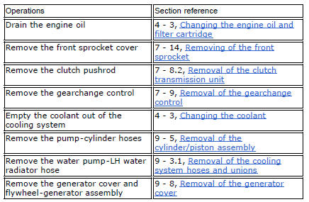
Ducati Diavel Service Manual: Removal of the gear selector lever
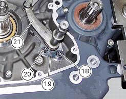
Unscrew and remove the fixing screws (18) and (20) of the complete gear selector lever (21) and collect the spacer (19).
Remove the gearchange mechanism complete with the shaft, spring, and stop plate.
Important
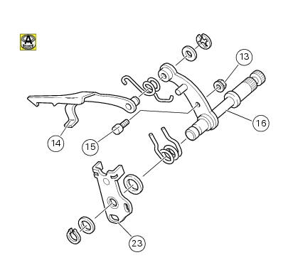
Visually inspect the gear selector claw (14) for wear, particularly around the area where it contacts the selector drum.
If it proves necessary to change components, disassemble the gear selector lever as shown in the exploded view.
Reassemble the gear selector lever orienting the eccentric pin (15), suitably lubricated, in such a way that the lever arm (16) is positioned centrally with respect to the shoulders of the stop plate (23).
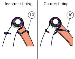
Check that the spring (10) is installed correctly as shown in the figure.
Tighten the nut (13) to a torque of 10 nm (min. 9 Nm - max. 11 Nm) (sect. 3 - 3, Engine torque settings).
 Gearchange mechanism
Return spring
Washer
Special screw
Gear pawl assembly
Interlock plunger holder
Sealing washer
Detent ball spring
Ball
Circlip
Selector claw return spring
Shim washer
Ring
...
 Disassembly of gear interlock plunger and pawl assembly
Unscrew the interlock plunger screw (5) and remove the seal (6), spring (7)
and the detent ball (8).
Unscrew the clutch-side crankcase half screw (3) and remove the pawl (4),
washer (2) a ...
Other materials:
Reassembling the front footrest brackets
To reassemble the brackets (6) and (21) carry out the removal procedure in
the reverse order; tighten the screws (7) to a
torque of 25 nm +/- 10% (sect. 3 - 3, Frame torque settings).
...
Refitting the engine
Refitting is the reverse of removal.
Important
Apply recommended grease and tighten the special screws (6) to a torque of
60 nm +/- 5% (sect. 3 - 3, Frame torque
settings).
Tighten the nuts (3) to a torque of 48 nm +/- 5% (sect. 3 - 3, Frame torque
settings).
Warning
For the assembly seque ...
Flywheel - alternator
Screw
Alternator stator
Plug
Sealing ring
O-ring
Cover
Screw
Aluminium gasket
Screw
Bracket
Locating bush
Screw
generator cover
Flange
Flanged nut
Plane washer
Flywheel
Washer
Inner ring
Needle roller bearing
Electric starter driven gear
Starter clutc ...