
Ducati Diavel Service Manual: Removal of the generator cover
Note
This operation is described for an engine removed from the frame since all reassembly procedures are easier with the engine on the bench.
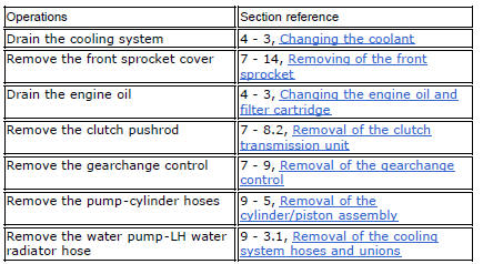
Disconnect the connector (a) from the generator cable.
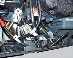
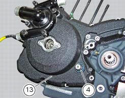
Unscrew the two retaining screws (7) of the centre cap (6) over the end of the crankshaft.
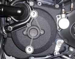
Loosen the screws (1) and (12) securing the generator cover (13).
Use tool number 88713.1749 And fix it to the holes (a) of the previously removed screws (7).
Turn the tool shaft slowly to separate the cover (13) from the lh crankcase half.
There is a seal (4) on the cover (13) in correspondence with the gearchange lever shaft that may be damaged when removing the generator cover.
Always check the condition of this sealing ring and renew it if damaged.
 Flywheel - alternator
Screw
Alternator stator
Plug
Sealing ring
O-ring
Cover
Screw
Aluminium gasket
Screw
Bracket
Locating bush
Screw
generator cover
Flange
Flanged nut
Plane washer
F ...
 Disassembly of the generator cover
Undo the three stator retaining screws (25) and the two retaining screws (9)
of the two cable grommet bracket (10) from
inside the generator cover.
Remove the stator (2) and the cable grommet br ...
Other materials:
Removing outer components
Note
The following removal operations are required in order to renew and/or
clean the crankcase halves. If the original
crankcase halves are to be reused, then the removal of these components is not
essential.
Unscrew the screw (17) and remove the oil breather valve (1) with the o-rings
...
Electrical power for lighting and signalling devices
The front and rear running lights consist of led units with light conduits.
As a result, the light source is not visible as the
light is diffused through the surface of the light conduit.
These two images illustrate the front and rear running lights with light
conduits.
The figure ...
Removal of the tool tray
To remove the tool tray unit from the lateral footrests, loosen the screws
(40) and remove the splashguard (20).
Undo the screws (15) and remove the cover (16).
Move the wiring branch from the seat (s) on the tool tray.
Loosen the screws (24) to remove the tool tray unit (23) from ...