
Ducati Diavel Service Manual: Removal of the oil pump
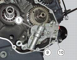
Undo and remove the screws (9) and (10) securing the pump assembly.
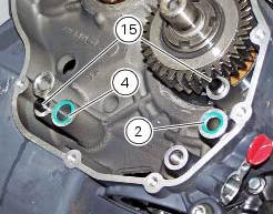
Remove the oil pump assembly (1) and extract the o-rings (2) and (4) from the crankcase half together with two locating bushes (15).
 Oil pump
Complete oil pump assembly
O-ring
Circlip
O-ring
Pump body
Circlip
Reducer bush
Spring washer
Screw
Screw
Spring washer
Pump drive gear
Key
By-pass plug
Locating bus ...
 Disassembly of the oil pump
Hold the oil pump (1) in a vice taking care not to damage the drive gear
(12).
Warning
Make sure that vice jaws are faced with soft material.
Remove the plug (14) and extract the spring (16) ...
Other materials:
Removing of the front sprocket
Undo the screws (11) and remove the chain cover (10).
Loosen the chain (sect. 4 - 3, Adjusting the chain tension).
Remove the chain with the tool code 88713.1344.
The tool is composed of a holder (a), punch (b), body (c) and two wrenches (d)
and (e).
Fit the link to be opened into th ...
Removing the flywheel - generator assembly
Use the tool 88713.3367 Fixed to the m10 side stand fixing holes (d).
Secure the tool to the flywheel with the screws (e).
Unscrew the alternator-flywheel retaining nut (15).
Warning
While unscrewing the nut, apply axial pressure to the socket to
avoid damage or injury in the event of the ...
Specific operating strategies
Idle speed
No electric motor is used for idle speed regulation (bypass is modulated
instead with the throttle valve), as idle speed
control is effected by the ride-by-wire system. Idle speed is maintained by the
control unit when the speed drops below a
specific threshold and when the clutch ...