
Ducati Diavel Service Manual: Removal of the rear brake disc
Remove the rear eccentric hub (sec. 7 - 13, Removal of the rear wheel eccentric hub and rear wheel shaft).
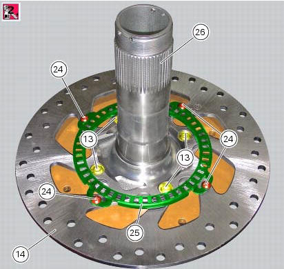
Undo and remove the four fixing screws (13) of the brake disk to the wheel axle and remove the rear brake disk (14).
Loosen the four screws (24) and remove the rear phonic wheel (25).
The brake disc must be perfectly clean, with no rust, oil, grease or other dirt and no deep scoring.
To check the wear limit of the brake disk refer to sec. 3 - 1.1, Hydraulic brakes.
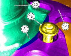
Place the rear brake disc (14) on the rear wheel shaft (26), by orienting the bevelled edges (s) faced upwards.
Fix the disc by starting the screws (13) with prescribed threadlocker.
Note
Make sure to centre the screw heads in the relevant seats on the brake discs.
Tighten the screws (13) to a torque of 27 nm +/- 10% (sect. 3 - 3, Frame torque settings), in the sequence 1-2-3-4.
Position the phonic wheel (25) on the brake disc (14) by orienting it as shown in figure.
Fix the phonic wheel (25) by starting the screws (24) with the recommended threadlocker.
Tighten the screws (24) to a torque of 5 nm +/- 10% in a crossed-pattern sequence.
Refit the rear eccentric hub as described in sec. 7 - 13, Removal of the rear wheel eccentric hub and rear wheel shaft.
 Removal of the rear brake calliper
Important
The brake manufacturer advises against any servicing of the internal
components of brake callipers or the master cylinder.
Incorrect overhaul of these critical safety components can en ...
 Refitting the rear brake calliper
When replacing the brake pipes (33) or removing one of the rear braking
system components, pay special attention to the
position of the couplings on the pump and the calliper.
Warning
If incorrec ...
Other materials:
Refitting the starter motor gear
Position the washer (20) and the gear (19) in the pin (21) and take the pin
into contact with the crankcase half.
...
Removal of the air filters
Work on the vehicle right side, loosen screws (3) that secure the intake duct
(2) to the airbox, and the radiator retaining
screw (a); recover the washer (b).
Remove the intake duct (2).
Proceed in the same way to remove the lh intake duct (6), and disconnect the
connector (c) ...
Removal of the front brake system
Note
For the abs front braking system, also refer to sect. 7 - 5, Abs system
operating information, sect. 7 - 6, System
components, sect. 7 - 7, Abs components maintenance.
Undo the special screw (3), collect the sealing washers (4), and release the
front brake master cylinder assembly (1 ...