
Ducati Diavel Service Manual: Removal of the steering head components
Note
All parts fitted to the top and bottom yokes, including the wiring and control cables, can remain on the motorcycle provided they do not hinder the following operations.
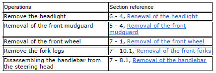
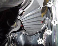
Loosen the screws (19) securing the supports (21) and (23) of splashguard (22) to the air conveyors (t).
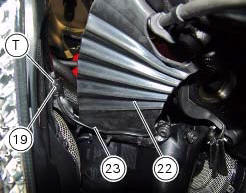
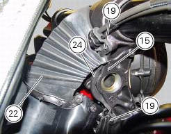
Loosen the screws (19) securing the front support (24) of the splashguard (22) to the bottom yoke (15).
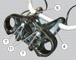
Loosen the screws (v) to free the cable grommets (p) from the steering head (2).
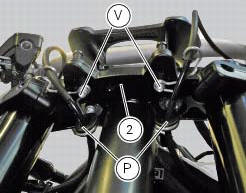
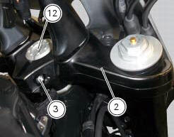
Loosen the screw (3) securing the steering head (2) to the steering head nut (12).
Remove the steering head (2).
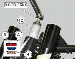
With the service tool no. 88713.1058 Loosen the nut (12) and unscrew it from the steering shaft.
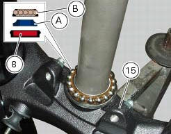
Slide the seal (8), the inner ring (a) and the ball race (b) of the upper bearing (6) off the steering shaft.
Remove the bottom yoke (15) complete with the steering shaft from the frame tube.
Remove the ball race (b) of the lower bearing (6).
The inner race (a) of the lower bearing (6) and the relative oil seal (8) will remain on the steering shaft.
Using a universal puller (see figure) remove the inner race (a) and the spacer (13) from the steering shaft, taking care not to damage the seat.
Important
Once removed, the seals (8) and the bearings (6) must not be refitted.
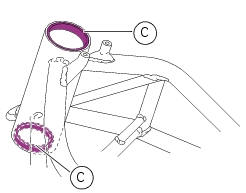
Using a suitable punch, remove the outer bearing races (c) from the steering head. Proceed with extreme care to avoid damaging the seats.
Disassembly of the steering head
Loosen and remove the screws (7), washers (11) and the lower u-bolts (4) and (5) from the steering head.

Reassembly of the steering head
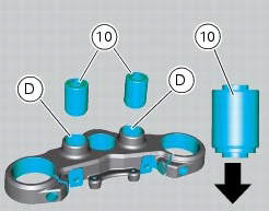
If the spacers (10) were removed from the steering head, lubricate with silicone spray.
Seat the spacers (10) square in the bores (d) in the steering head, orienting them as shown in the figure.
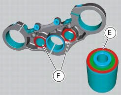
Important
To drive in the spacers (10), use a drift that bears only on the outer ring (e) while applying a counterforce on zone (f) on the underside of the steering head.
On completion of the operation, clean all excess lubricant from the components.
Locate the lower u-bolts (4) and (5) on the steering head.
Fit the screws (7) complete with the washers (11 in the lower u-bolts (4) and (5).
Tighten the screws (7) to a torque of 45 nm +/-5% (sect. 3 - 3, Frame torque settings).
 Steering angle adjustment
Loosen the nuts (17) and adjuster screws (16) on both sides of the bottom
yoke.
Use a 6 to 6.5 Mm spacer (a) fitted to the fork outer tube, or use a gauge.
Turn the front forks to the righ ...
 Refitting the steering head components
Important
The steering tube bearings (6) are identical but in no case may their
components be swapped around during reassembly.
Clean all contact surfaces and lubricate with the recommended grease ...
Other materials:
Trip 2 meter
This function shows the distance travelled since the trip meter was last
reset (in km or miles depending on the specific
application).
Press and hold (1) "s" for 3 seconds while in this function to reset the trip
odometer.
When the reading exceeds 9999.9, Distance travelled is reset and t ...
Protective apparel
Always wear a helmet. Most motorcycle accident fatalities
are due to head injuries.
For safety eye protection, gloves, and high top, sturdy boots
should also be worn.
The exhaust system becomes very hot during operation,
never touch the exhaust system. Wear clothing that fully
covers your ...
Tips for use on the road
Activate the dtc, select level 8 and ride the motorcycle in
your usual style; if the level of dtc intervention seems
excessive, try reducing the setting to levels 7, 6, etc., Until
you find the level that suits you best.
If changes in the grip conditions and/or circuit characteristics
and/or ...