
Ducati Diavel Service Manual: Removal of the swingarm
Before removing the parts in question, you must first carry out the following operations:
Remove the rear wheel eccentric hub as described in chapter "removal of the rear wheel eccentric hub and rear wheel shaft" of this section.
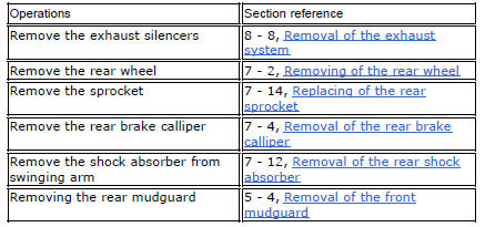
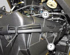
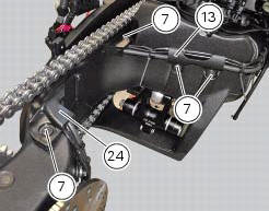
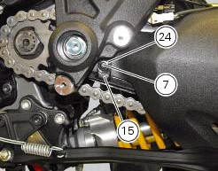
Loosen screws (7) and remove the hose grommets (13), (15) and (24).
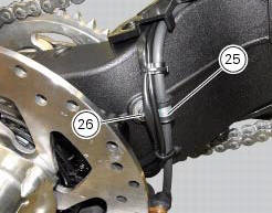
Release the rear brake hose, the rear speed sensor cable, and the rear wiring from the swingarm, by loosening the screws (26) and retrieving the cable grommets (25).
You can check the play in the swingarm bearings while the swingarm (8) still installed on the motorcycle frame.
Grasp the rear of the swingarm (8) and try to move it in the four directions shown by the arrows.
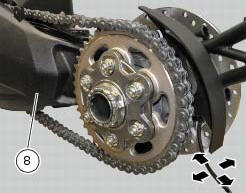
Any abnormal movement is a sign of worn bearings that could cause instability when riding.
To check the free play of the support bearings, refer to sect. 7 - 1, Wheel bearings.
Once the play in the swingarm bearings has been checked, the swingarm (8) may be removed from the motorcycle.
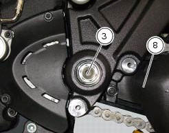
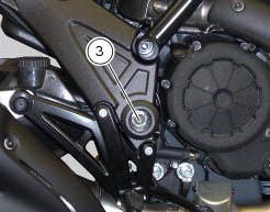
Keep the swingarm shaft (1) blocked with the screws (3) on the bike lh side and loosen at the same time the screw (3) on the opposite side: keep washer (2).
Using the punch 88713.1074, Fully extract the swingarm pivot.
Remove the swingarm (8) assembly from the frame.
Inspecting the swingarm pivot
Before refitting the swingarm pivot shaft (1), check it carefully for distortion.
Roll the pin on a reference surface and measure maximum distortion using a feeler gauge (sect. 3 - 1.1, Rear wheel).
 Refitting the rear wheel eccentric hub and rear wheel shaft
Refitting is the reverse of removal, with attention to the following points.
If the calliper bracket locating pin (14) was removed, apply the recommended
threadlocker on reassembly.
Tighten th ...
 Overhauling the rear swingarm
Inside the swingarm (8), in correspondence with the pivot point on the frame,
there is a pair of ball bearings (10) and a
spacer (11) on the rh side, and a pair of roller bearings (6), with sealing ...
Other materials:
Removal of the exhaust system
Remove the silencer, as described in the paragraph "removing the silencer" of
this section.
Loosen the screws (28) and remove the exhaust by-pass valve cover (27).
Turn the exhaust valve pulley (a) to facilitate the throttle cable (25)
output.
Release the end fitting (b) of the cable ...
Refitting the rear wheel eccentric hub and rear wheel shaft
Refitting is the reverse of removal, with attention to the following points.
If the calliper bracket locating pin (14) was removed, apply the recommended
threadlocker on reassembly.
Tighten the pin (14) to the torque of 33 nm +/- 5% (sect. 3 - 3, Frame torque
settings).
If previously ...
Refitting the seat
Note
Apply recommended grease to the hole (a) of latch (6).
Fit the seat (1) as follows: insert the tabs (b) (on the front side) under
the rubber pads (c) of the gloves compartment;
then push the seat rear side until hearing the lock latch click.
...