
Ducati Diavel Service Manual: Removing of the abs control unit
Drain the hydraulic fluid that is inside the front and rear braking system tubes by disconnecting them from the master cylinder and the calliper (sect. 4 -3, Changing the brake fluid).
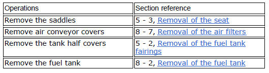
Disconnect the connector (a) of the abs control unit (6).
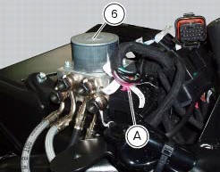
Loosen the screws (16) that retain the abs control unit support (12) and remove it from the vehicle.
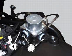
Undo the four special screw (17) fixing the pipes (10), (9), (8) and (7), on the abs control unit (6), removing the gaskets (11).
Warning
Every time that gaskets (11) are removed, they must be replaced with new gaskets (11).
Important
Do not open the abs control unit: if it is faulty, replace it.
Note
If it is necessary to replace one or more pipes, follow the instructions indicated in paragraph "flexible wiring/hoses positioning" of this section.
 Replacing the rear phonic wheel sensor
Disconnect the rear abs sensor (5) connector (c) from the main electric
wiring.
Open all the retainer clamps of the rear abs sensor cable (5): refer to table of
sect. 7 - 6, Flexible wiring ...
 Refitting the abs control unit
If the brake hoses (7), (8), (9) and (10) on the abs control unit are changed
or removed, ensure that the fittings on the
control unit are positioned correctly.
Warning
If incorrectly positioned, ...
Other materials:
Disassembly of rear shock absorber - rocker arm - linkage assembly
Undo the screw (15) and remove the rear shock absorber (11) from the rocker
arm (18).
Undo
Undo the screw (14) and the nut (21) and remove the linkages (10) and (12)
from the rocker arm (18).
The rocker arm movement is obtained by needle roller bearings (9) rotating on
a spacer (1 ...
Rear shock absorber assembly
Special screw
Screw
Nut
Grub screw
Bush (right)
Bush (left)
Screw
Sealing ring
Roller bearing
Linkage (left)
Shock absorber (rear)
Linkage (right)
Spacer
Special screw
Screw
Bush
Ball joint
Rocker arm assembly
Support
Washer
Nut
Screw
Shock absorber ...
Vehicle pre-delivery
Transport packaging integrity check (if required);
Removal from the transport packaging (if required);
Motorcycle integrity check;
Check of the supplied kit completeness (refer to the parts list supplied
together with the bike packaging);
Only if the bike is supplied in a crate: handle ...