
Ducati Diavel Service Manual: Removing of the cylinder head pulley/fixed tensioner
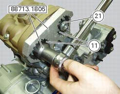
Insert the tool code 88713.1806 In the pulleys to lock their rotation and use the bush supplied to loosen the fixing nuts (21) of the pulleys.
important
On reassembly, always use new nuts.
Remove the nuts (21) and the pulleys (11) from the camshafts.
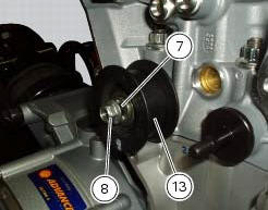
Loosen the nut (8), and remove the washer (7) and the fixed tensioner (13).
Repeat the same procedure to remove the other pulley.
Removal of the tensioner and idler pulley mounting studs
Using the tool code 88713.1821, Remove the tensioner pins (12) from the cylinder heads.

 Removal of the movable tensioner/timing belt
Loosen the nut (8) and remove the washer (7) and the tensioner pulley (9)
from the pin (12) on the cylinder head.
Remove the timing belt (14) from the horizontal cylinder assembly.
Important
If ...
 Disassembly of the camshaft pulleys
Unscrew and remove the screws (22).
Slide off the washer (23).
Withdraw the camshaft pulley (11) from the spacer flange (24).
...
Other materials:
General maintenance indications
Useful tips
Ducati recommends that you follow the instructions below in order to prevent
problems and obtain the best end result:
When diagnosing faults, primary consideration should always be given to
what the customer reports about motorcycle
operation since this information can highli ...
Overhaul of the gearbox
Check the condition of the front coupling dogs of the gears. They must be in
perfect condition and with no sign of wear on
the edges of the teeth.
The idler gears must rotate freely on their shafts.
When refitting, make sure the circlips are correctly positioned.
Check the needle roller ...
Communication antenna
Introduction
The communication antenna enables the hands free system to detect and
communicate with the active or passive key.
The active key is detectable within a range of 1.5 Metres, whereas the passive
key (or active key with flat battery) can
only be detected if placed in contact with ...