
Ducati Diavel Service Manual: Removing of the rear brake control
Warning
The brake master cylinder manufacturer advises against servicing the brake master cylinder due to the safety critical nature of this component.
Incorrect overhaul can endanger the rider and passenger.
Maintenance operations on these units are limited to renewal of the following parts: control lever, fluid reservoir assembly and relative fasteners and master cylinder fasteners.
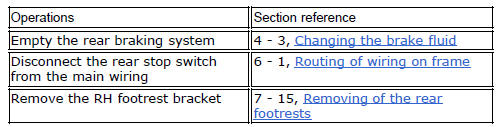
Note
For the abs front braking system, also refer to sect. 7 - 5, Abs system operating information, sect. 7 - 6, System components, sect. 7 - 7, Abs components maintenance.
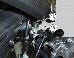
Slide the adjusting rod (18) out of the rear brake master cylinder (16).
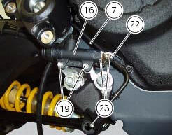
Loosen the special screw (22) from the master cylinder (16); slide out the hose (7) and recover the sealing washers (23).
Loosen the rear brake master cylinder (16) retaining screws (19) and remove it from the vehicle.
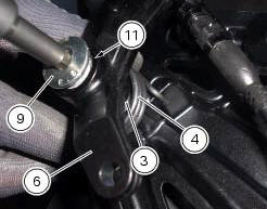
Undo the fixing pin (9) of the brake lever (6), collecting the spring (4).
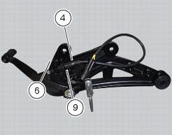
Remove the brake lever (6) and collect the pin (9), the washer (3), the bush (10) and the o-ring (11).
 Rear brake
Rear speed sensor (abs)
Screw
Washer
Spring
Brake switch (rear)
Brake lever (rear)
Rear pump - control unit pipe
Sealing washer
Pin
Bush
O-ring
Screw
screw
Rear brake ...
 Disassembly of the rear brake control
The brake master cylinder is supplied only as a complete unit; internal
components cannot be replaced.
To disassemble the master cylinder's outer parts, follow the indications given
in the expl ...
Other materials:
Testing the battery charging system
Note
The on-screen icons used during this procedure are explained in a table at
the end of this section.
You can determine the engine rpm required for generator to produce just
enough current to charge battery, feed the
injection ignition system and all electric items fitted to motorcycle. Wh ...
Overhauling the front brake components
Important
Critical safety components. The brake calliper manufacturer recommends
that you do not attempt to service the internal
components of the brake callipers. Incorrect overhaul of this component could
endanger rider safety.
Operations should be limited to renewal of the pads, fasteners ...
Removing of the abs control unit
Drain the hydraulic fluid that is inside the front and rear braking system
tubes by disconnecting them from the master
cylinder and the calliper (sect. 4 -3, Changing the brake fluid).
Disconnect the connector (a) of the abs control unit (6).
Loosen the screws (16) that retain the abs ...