
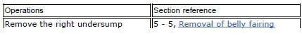
Ducati Diavel Service Manual: Removing of the side stand
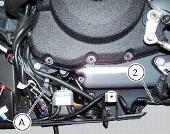
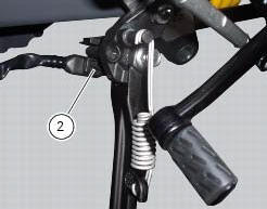
Disconnect connector (a) of the stand switch (2) from the main wiring.
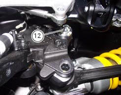
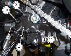
Loosen the screws (3), (10), (11) and (12) securing the stand bracket (4) to the engine and remove the complete side stand assembly.
Disassembly of the side stand
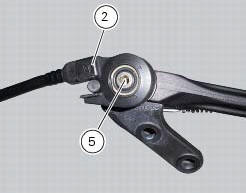
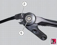
Undo the fixing screw (5) and remove the side stand switch (2).
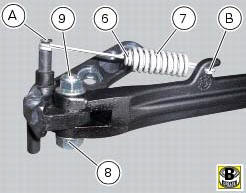
Release the side stand return springs (6) and (7) of the fasteners (a) and (b).
Undo the stand fixing pin (9) to the bracket and remove the side stand (1) and the nut (8).

Inspecting the side stand
Fit the side stand leg to the bracket and check that there is no excessive clearance. Ensure that the ends of the side stand are not bent with respect to the shank.
A side stand which shows signs of cracking must be renewed immediately.
To check the switch (2) refer to sec. 6 - 6, Checking the side stand switch.
Reassembling of the side stand
Insert the side stand (1), properly greased, in the bracket (4) and fix it with the pivot (9) and the nut (8).
Tighten the nut (8) to the torque of 20 nm +/- 10% (sect. 3 - 3, Frame torque settings).
Position the side stand return springs (6) and (7) and fix them to the fasteners (a) and (b) on the bracket and on the stand.
Set switch (2) to plate (4) by inserting sensor pin (c) into side stand hole (d) and making sure side stand pin (e) matches with groove (f) on sensor.
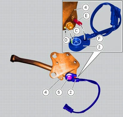
Fit the retaining screw (5) with recommended threadlocker and tighten it to a torque of 5 nm +/- 10% (sect. 3 - 3, Frame torque settings).
 Stands
Side stand
Side stand switch
Screw
Plate
Screw
Inner spring
Outer spring
Nut
Rotation pivot
Screw
Screw
Screw
Nut
Clearance adjuster
Spare parts catalogue
Diavel a ...
 Refitting the side stand
Place the stand plate on the rear shock absorber support; bring adjuster (14)
in line with bracket (s) and start the screw
(12) in the nut behind the bracket (s).
Insert the screws (11), (3) and ...
Other materials:
Refitting the rear mudguard
Place the rear mudguard (8) on the swingarm, fitting the screws (9) with
recommended threadlocker.
The screw (9) in the bottom hole of the rear mudguard (8) must be installed with
the washer (r).
Tighten the screws (9) to a torque of 5 nm +/- 10% (sect. 3 - 3, Frame torque
settings).
...
Removal of the timing belt covers
Loosen the screws (4) securing the central external cover (1) and remove it
from the central side.
Undo the fixing screws (4) of the external cover (25) and remove it from the
vertical thermal unit.
Undo the fixing screws (4) of the external cover (3) and remove it from the
horizonta ...
Lap registration function
This function describes the "lap" time registration.
If the function is activated (see "lap activation/deactivation
description), the lap time can be registered as follows:
Pressing the flash headlight button (11, fig. 12) The first
time starts the "lap timer" for ...