
Ducati Diavel Service Manual: Removing the electrical components support
Remove the following elements located inside the electrical components support:
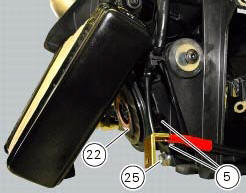
- The battery fixing bracket (4) and the battery (14) as specified under section 6 - 2, battery;
- The voltage regulator (3) as specified under section 6 - 2,rectifier-regulator;
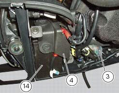
- The solenoid starter (18) as specified under section 6 - 3,solenoid starter;
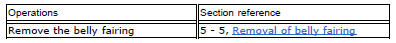
Remove the connector (a) of horn (22) from the main wiring.
Undo the screw (25) and remove the horn (22) from the vehicle.
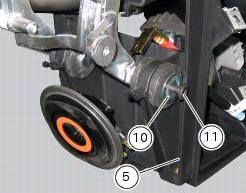
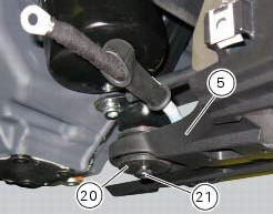
Loosen screws (11) and (21) and recover the washer (10) and the spacer (20).
Remove the electrical components support (5).
Pay attention to the main wiring branch and to any other wiring inside of it.
Refer to the tables reported in this section for the components position.
 Electrical components support
Clip
Screw
Voltage regulator
Battery fixing bracket
Battery support
Vibration damper mount
Hose clip
Vibration damper mount
Clip
Washer
Screw
Cover
Cable grommet
Batte ...
 Reassembling the electrical components support
Check the presence of clips (1), (9) and (24) on the support (5).
Check the presence of rubber pads (6) and (8) and of cable grommet (7).
Check that the voltage regulator (3) and the solenoi ...
Other materials:
Reassembly of the crankcase halves
If removed, apply threadlocker on the screw (36), insert it with the washer
(37) on the crankcase half and tighten it to The torque of 8 nm
(min. 7 Nm - max. 9 Nm) (sect. 3 - 3, Engine torque settings).
If removed, apply threadlocker on the dowel thread (35), tighten it to a
torque of 20 ...
Removal of the cylinder heads
Using the tool code 88713.2676, Undo the nuts (21) on the cylinder head stud
bolts.
Remove the cylinder head nuts (21) and special washers (22).
Remove the cylinder head assembly by lifting it off the engine studs.
Repeat the same procedure for the other cylinder head. ...
How to turn the motorcycle off
To turn the motorcycle off, turn the switch from "run on" to "run off". The
engine stops. To switch the dashboard off,
push the on/off switch downwards. When released, the switch automatically
returns to the "run off" position.
Push the switch downwards to switch the engine off and enter " ...