
Ducati Diavel Service Manual: Removing the front footrest brackets
Note
The assembly of the front footrests is described only for the right one (2) but it is the same also for the left one.
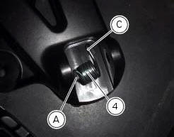
Place the spring (4) bringing the end (a) onto the footrest (2).
Place the footrest (2) in the correct position, by inserting the end (c) of the spring (4) in the hole (d) of the frame plate.
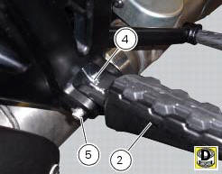
Apply the recommended grease to the pin (3).
Insert pin (3) orienting it as illustrated.
Lock the pin by inserting the circlip (5).
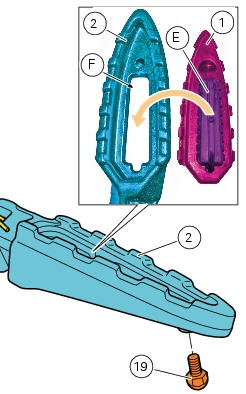
If previously removed, refit the rubber footrest (1) on the footrest (2), inserting pad (e) into the seat (f) in the footrest (2) until it becomes engaged.
Note
To better insert the rubber footrest (1) use lubricant specific for rubber.
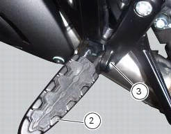
Start the screw (19) on the bottom side of the footrest (2) and tighten to the specified torque.
 Refitting the front footrests
Note
The assembly of the front footrests is described only for the right one
(2) but it is the same also for the left one.
Place the spring (4) bringing the end (a) onto the footrest (2).
Place ...
 Reassembling the front footrest brackets
To remove the front rh footrest bracket (6) it is necessary to remove the
rear brake master cylinder reservoir (by leaving
it connected to the braking system), and the rear brake lever from the bra ...
Other materials:
Replacing the tank flange and fuel sensor
Loosen the screws (19) securing the fuel tank flange (20).
Remove the flange (20) from the tank (20).
Recover the seal (21).
Undo and remove the two fixing screws (g) and move the protection (f).
Before reassembly, carefully remove any deposits or scale from all parts.
Note
The flang ...
Belly fairing
Rh belly fairing
Lh belly fairing
Special screw
Nylon washer
Screw
Central belly fairing
Oil cooler shield
Special screw
Clip
Washer
Clip
Screw
Bracket
Screw
Spare parts catalogue
Diavel abs belly fairing
Diavel carbon
abs
belly fairing
Important
Bold refere ...
Battery
Battery safety rules
Warning
Before carrying out any operations on the battery, keep in mind the
safety standards (sect. 1 - 3, General safety rules).
When under charge, batteries produce explosive gases. Keep batteries away from
heat sources, sparks or open flames.
Instructions for use
T ...