
Ducati Diavel Service Manual: Removing the timing belt driveshaft pulleys
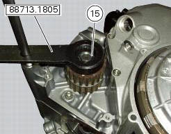
Use the tool code 88713.1805 To hold the driving pulley on the engine crankcase against rotation.
Important
If this operation is carried out with the engine installed in the frame, hold the driveshaft pulleys against rotation using the tool code 88713.2011 Mounted on the alternator cover.
Loosen the nut (15) using the socket supplied with the service tool.
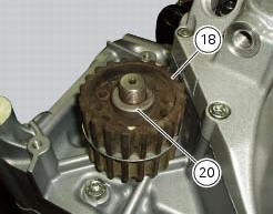
Remove the nut (15), the spacer (20) and the outer pulley (18).
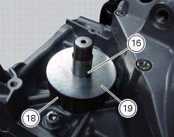
Remove the first woodruff key (16) from the timing belt driveshaft.
Remove the intermediate spacer (19) and the inner pulley (18).
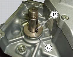
Remove the inner spacer (17) and second woodruff key (16) on the timing belt driveshaft.
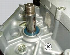
It is now possible to remove the circlip (10) on the driveshaft.
 Disassembly of the camshaft pulleys
Unscrew and remove the screws (22).
Slide off the washer (23).
Withdraw the camshaft pulley (11) from the spacer flange (24).
...
 Refitting the timing belt driveshaft pulleys
To fit the circlip (10) in the driveshaft seat, use the tool code 88713.2834.
Install the inner spacer (17) on the driveshaft, taking care to align the
notch in the spacer with the slot for the ...
Other materials:
Engine torque settings
*Dynamic safety-critical point; tightening torque must be within nm +/-5%.
Note
For product specifications and symbols, refer to paragraph "product
specifications" (sect. 1 - 2). ...
Removal of the shock absorber support
Remove the rear brake master cylinder (sect. 7 - 4, Removing of the rear
brake control).
Remove the rear shock absorber (see removal of the rear shock absorber of this
section).
Loosen the screws (2) and (7) and their nuts (35).
Remove the side stand (sect. 7 - 16, Removing of the ...
Lubricating cables and joints
Check the outer sheath of the throttle control and cold start
lever cables for damage at regular intervals. The outer plastic
cover should not be flattened or cracked. Operate the
controls to make sure the inner cables slide smoothly inside
the outer sheath: if you feel any friction or catching, ...