
Ducati Diavel Service Manual: Removing the valve rocker arms
With the cylinder head in the condition described in the previous paragraph, remove the rocker arms.
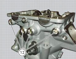
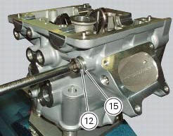
Unscrew the eight plugs (12) and recover the seals (15).
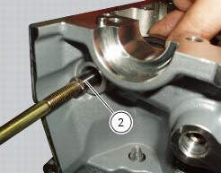
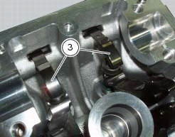
Using an m6 screw, withdraw the shafts (2) of the opening rocker arms (3) on the exhaust and intake sides.
Remove the opening rocker arms (3).
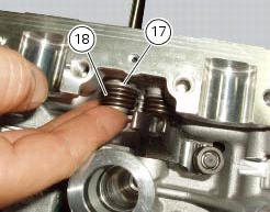
Using the claw of the rocker arm spring tensioning kit 88713.2069 Installed between the spring and the inner wall of the cylinder head, move the straight end of the rocker arm return spring (19) and (18) and insert it in the drilled shaft.
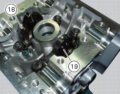
Use the shaft to slide the end of the spring into its final position.
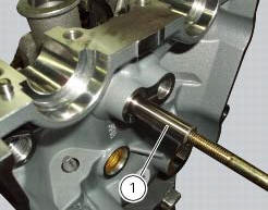
Using an m6 screw, withdraw the shafts (1) of the closing rocker arms on the exhaust and intake sides.
Remove the closing rocker arms (4) and (16), the springs (18) and (19) with the spacers (17).
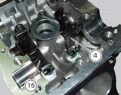
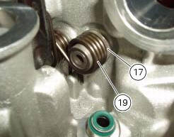
Carry out the same operation to remove the closing rocker arms (4) and (16), the springs (24) and (25) with the spacers (23).
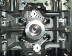
Remove the sealing rings (8) from the ends of the valve guides.
Repeat the same procedure for the other cylinder head.
 Removing the valves
Raise the rocker arm (3) and remove the opening shim (5) from the valves with
a pair of pliers.
Push down the closing rocker arms (16) and (4) and the closing shim (7).
Remove the half r ...
 Overhaul of cylinder head components
Cylinder heads
Remove any carbon deposits from the combustion chamber and its ducts.
Remove any scale from the coolant ducts.
Check for cracking and inspect the sealing surfaces for scoring, ri ...
Other materials:
Battery voltage indicator (battery)
This function describes the battery voltage indicator.
To access the function it is necessary to view the "setting" menu page 48, using
button (1, fig. 14) ?"" or (2, fig.
14) ?" " select the "battery" function
and press the reset
button (12, fig. 12 ...
Removal of the rear shock absorber
Loosen the screws (22) and remove the assembly (34) from the frame.
Loosen the screws (27) and remove the tank unit (s) of the shock absorber
from the support (19).
Hold the lh bush (6) and loosen the rh bush (5) to release the front side of
the shock absorber assembly.
Un ...
Removing the timing belt driveshaft pulleys
Use the tool code 88713.1805 To hold the driving pulley on the engine
crankcase against rotation.
Important
If this operation is carried out with the engine installed in the frame,
hold the driveshaft pulleys against rotation using the
tool code 88713.2011 Mounted on the alternator cover.
Lo ...