
Ducati Diavel Service Manual: Renewal of the headlight
Disconnect the headlight connectors (a) from the main wiring (refer to the tables of paragraph "routing of wiring on frame", sect. 6 - 1).
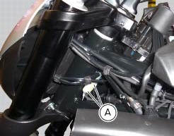
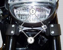
Loosen nuts (2) that fix the front optical unit to the bottom yoke, and recover the washers (3).

Remove the complete front optical unit by sliding it upwards and releasing it from pins (b) of the supporting bracket.
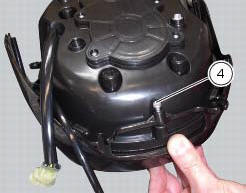
Release the headlight from the front optical unit support by loosening the screws (4) and recovering the washers (5).
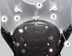

Refit the headlight on the front optical unit support, insert the spacers with collars (5) and the screws (4).
Apply the recommended threadlocker to the screws (4).
Tighten the screws (4) to a torque of 6 nm +/- 10% (sect. 3 - 3, Frame torque settings).
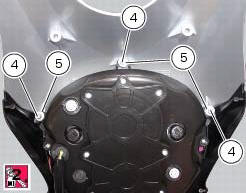
Check for the pads (6) on the supporting bracket.
Apply the recommended threadlocker to the screws (4).
Tighten the screws (4) to a torque of 6 nm +/- 10% (sect. 3 - 3, Frame torque settings).
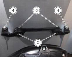
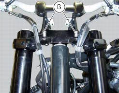
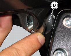
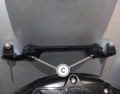
Refit the front optical unit by placing its lower part on the pads (d) and inserting the pins (b) into the eyelets (c) of the supporting bracket.

Fix the front optical applying a torque of 10 nm +/- 10% (sect. 3 - 3, Frame torque settings) to the nuts (2) with washers (3).
Reconnect the headlight connectors (a) to the main wiring (refer to the tables of paragraph "routing of wiring on frame", sect. 6 - 1).


 Changing bulbs
Changing the headlight bulbs
Before replacing a burnt out light bulb, ensure that the replacement bulb has
the same voltage and power rating as
specified for the lighting device in question (sect. ...
Other materials:
Refitting the radiator
The reassembly procedure is the same for both radiators.
Check for the nuts with clips (8).
Refit the rh radiator (13) on the frame and tighten the screws (4) and (5)
with the spacers (6) to a torque of 10 nm
+/-10% (sect. 3 - 3, Frame torque settings).
Connect the connections of ...
Transmission
Wet clutch controlled by the lever on left-hand side of the
handlebar.
Transmission from engine to gearbox primary shaft via spur
gears.
Front chain sprocket/clutch gearwheel ratio:
33/61
6-speed gearbox with constant mesh gears, gear change
pedal on left side of motorcycle.
Gearbox ou ...
Background setting function for the instrument panel on tank - dashboard 1
This function allows setting the "background" of the
instrument panel on tank.
To access the function it is necessary to view the "setting" menu page 48, using
button (1, fig. 14) ?"
" or (2, fig. 14) ?" " select the "back light" function
a ...