
Ducati Diavel Service Manual: Replacing the rear phonic wheel sensor
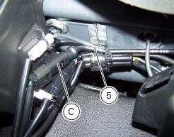
Disconnect the rear abs sensor (5) connector (c) from the main electric wiring.
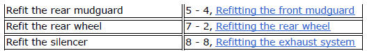
Open all the retainer clamps of the rear abs sensor cable (5): refer to table of sect. 7 - 6, Flexible wiring/hoses positioning.

Remove the rear abs sensor (5) from its seat on the rear calliper mounting bracket (e), undoing the retaining screw (1) and collect the calibrated gasket (3).
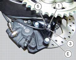
Before refitting, make sure that the contact parts between the rear abs sensor (5) and its seat are not damaged and are perfectly clean.
Fit the new rear abs sensor (5) on its seat inserting the screw (1).
Check the air gap between the new rear abs sensor (5) and the rear phonic wheel (d) as indicated in sect. 7 - 7, Adjusting of the air-gap phonic wheel sensor.
Fix the sensor to the calliper holder bracket tightening the screw (1) to a torque of 10 nm +/- 10% (sect. 3 - 3, Frame torque settings).
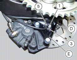
Connect the connector (c) to the main wiring.
Restore all the retainer clamps of the rear abs sensor cable (5): refer to table of sect. 7 - 6, Flexible wiring/hoses positioning.

 Replacing the front phonic wheel sensor
Disconnect the front abs sensor (2) connector (a) from the main electric
wiring.
Open all the retainer clamps of the front abs sensor cable (2): refer to table
of sect. 7 - 6, Flexible wiri ...
 Removing of the abs control unit
Drain the hydraulic fluid that is inside the front and rear braking system
tubes by disconnecting them from the master
cylinder and the calliper (sect. 4 -3, Changing the brake fluid).
Disco ...
Other materials:
Removal of the expansion tank
Loosen the clamp (6), open the hose guide (a) and slide the hose (7) out of
the radiator.
Open clamps (14) and release the hoses that pass through them.
Loosen the screws (16).
Remove the tank (12) with its hoses (7) and (20) and the support (15).
Loosen the clamp (19) to r ...
Menu 2 on/off function
This function turns off and back on the menu 2.
If menu 2 is disabled, the functions for average fuel consumption (cons.Avg),
instantaneous fuel consumption (cons.),
Average speed (speed avg), trip time (trip time) and air temperature (air) will
no longer be displayed in the "main
screen". ...
Refitting the primary drive gears and checking backlash
Fully degrease the crankshaft splined end and the corresponding spline on the
primary drive gear.
Position the spacer (c) onto the crankshaft.
Fit the driving gear (b) onto the crankshaft with the oil pump drive sprocket
facing the crankcase.
Temporarily secure the gear with the was ...