
Ducati Diavel Service Manual: Resetting turn indicators not possible - accessing dashboard menu not possible
Fault codes
Dds: no fault code displayed
Dashboard: no fault code displayed
Location of connections and components
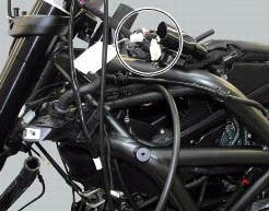
Location of left hand handlebar switchgear set connection.
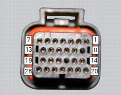
Pin numbering for wiring harness side dashboard connector.
Checks
Test turn indicator reset button function. When the button is pressed, there must be continuity between its two electric terminals (pin 3 and pin 1).
Check that there is a voltage of 5v on pin 1 of the turn indicator reset button arriving from dashboard pin 17.
Check the integrity of the electrical circuit and connections (short-circuits to ground, short-circuits to vdc, open circuits).
If none of the aforementioned tests identifies the problem, replace the dashboard.
Note
Check integrity of electric circuit - short-circuit to vdc = with dashboard on, using a voltmeter, a voltage is measured between the wire tested and ground.
Check integrity of electric circuit - short-circuit to ground = with the battery cables disconnected, using an ohmmeter, continuity is detected between the wire tested and ground.
Check integrity of electric circuit - open circuit = with the battery cables disconnected, using an ohmmeter, no continuity is detected between the two ends of the wire tested.
 Dashboard menu option scrolling not possible
Fault codes
Dds: no fault code displayed
Dashboard: no fault code displayed
Location of connections and components
Location of left hand handlebar switchgear set connection.
Pin numbering ...
 Gear indicator display on dashboard shows dashes, engaged gear not displayed
correctly, idle speed irregular
with gearbox in neutral
Gear indicator display on dashboard shows dashes, engaged gear not displayed
correctly, idle speed irregular
with gearbox in neutral
Fault codes
Dds: gear sensor diagnosis -> short circuit to ground or open circuit (s.C.
Gnd or c.O.) - Short circuit to vdc (s.C. Vdc)
- congruence (generic error - signal not correct).
Dash ...
Other materials:
Key-on/key-off using the key on the hands free lock with the passive key
Key-on can be performed by pressing the button (7) on the
hands free lock and with the presence of the passive key (4,
fig. 77).
Note
The passive key (4, fig. 77) Has a range of a few cm,
therefore the key (4, fig. 77) Must be positioned near the
antenna (2). Remove the seat (see "remova ...
Oil pump
Complete oil pump assembly
O-ring
Circlip
O-ring
Pump body
Circlip
Reducer bush
Spring washer
Screw
Screw
Spring washer
Pump drive gear
Key
By-pass plug
Locating bush
By-pass spring
By-pass valve
Spare parts catalogue
Diavel abs filters and oil pump
Diavel ...
Anti-pollution system and auto-adaptive strategy
Efficacy of the catalytic converter and oxygen sensors
To comply with current emissions legislation, the diavel is equipped with a
trivalent catalytic converter, which oxidises co
(carbon monoxide) and hc (unburnt hydrocarbons) and reduces nox (nitrogen
oxides).
The image shows the exhaus ...