
Ducati Diavel Owners Manual: Riding mode customisation
This function customises each riding style.
To access the function it is necessary to view the "setting"
menu page 48, using button (1, fig. 14) ?
or (2, fig. 14)
? select the "riding mode" function
and press the
reset button (12, fig. 12) To go to next page.
When accessing the function, the three riding modes appear
on the display; to customise the parameters, use button (1,
fig. 14)  or (2, fig. 14)
 to select the riding mode to
be changed and press the reset button (12, fig. 12) To
confirm.
The parameters that can be "customised" are "dtc" (ducati traction control) and "engine".
Any parameter change made is saved in the memory also after a battery-off.
To change the dtc parameters see the "dtc (ducati traction control)" paragraph page 52.
To change the engine parameters see the "engine (engine power control)" paragraph page 56.
The parameters set by ducati for each individual riding style can be restored with the "default" function.
To reset the "default" parameters see the "default (resetting ducati default parameters)" paragraph page 58.
 Note
Note
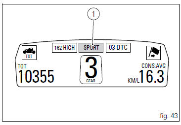
If the parameters have not been modified (customised) or are reset using the "default" function, when you quit the setting menu, in the "main" screen, the "background" indicating the riding style (sport, touring or urban) becomes blue (1, fig. 43).
 Warning
Changes should only be made to the parameters by people who are experts in motorcycle setup; if the parameters are changed accidentally, use the "default" function to reset the parameters.

 Setting menu
This menu is used to enable/disable and set some
motorcycle functions.
To access the "setting menu" press the button (2, fig. 14)
? for 3 seconds.
Note
When within this menu no ...
 Dtc (ducati traction control) setting function
This function allows you to customise the level of dtc
intervention (ducati traction control) or disable it for every
riding mode.
To access the function it is necessary to view the "setting ...
Other materials:
Battery voltage indicator (battery)
This function describes the battery voltage indicator.
To access the function it is necessary to view the ""setting" menu", using
buttons (1) "s" or (2) "t" select the "battery"
function and press the reset button (3) to confirm.
The information will be displayed as follows:
if battery vol ...
How to reset the pin code
The pin code can be reset with the dds, i.E. It can be brought to the same
condition it was in when the bike came out
the factory. It is possible to complete the procedure with the relevant pin code
reset function.
Once the pin code has been reset it will be necessary to store a new one. In ...
Key to wiring diagram
Right-hand handlebar switch
Immobilizer
Hands free relay
Hands free
Front fuse box
Right fan
Left fan
Fan relay
Fuel pump relay
Ride-by-wire relay (etv)
Injection control unit (ems)
Rear fuse box
Data acquisition/diagnosis
Starter motor
Fused solenoid
Battery
Wirin ...