
Ducati Diavel Service Manual: Routing of wiring on frame
The routing of the wiring has been optimised to ensure the minimum obstruction.
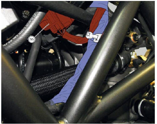
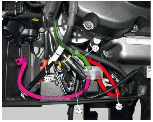
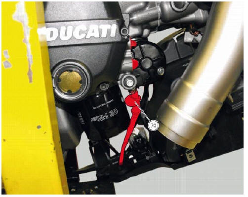
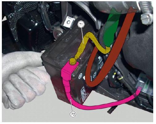
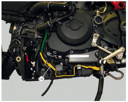
Each section is designed to prevent interference with parts that might damage wires or cause operating failures when riding. The plates on the following pages show the origins ("0" points) for correct re-routing of wiring and the locations of cable ties.
Each figure includes references to the plates showing the wiring routing or the item to which it must be connected.
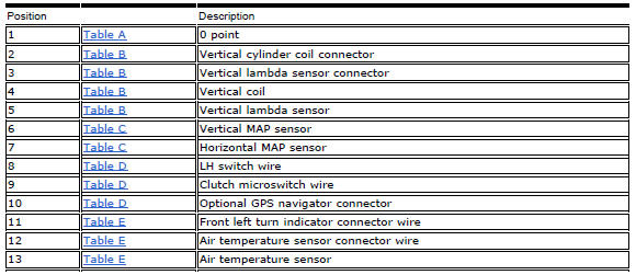
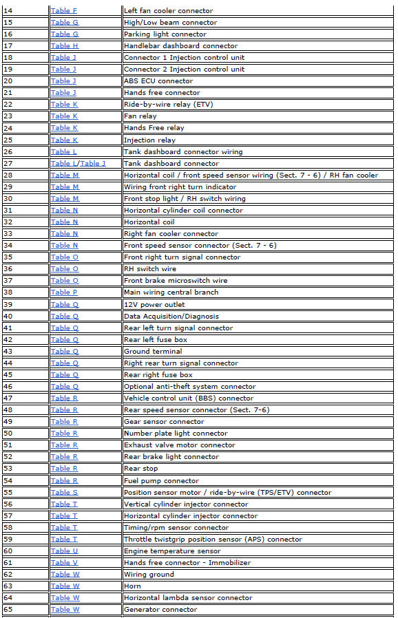
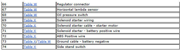
Table a
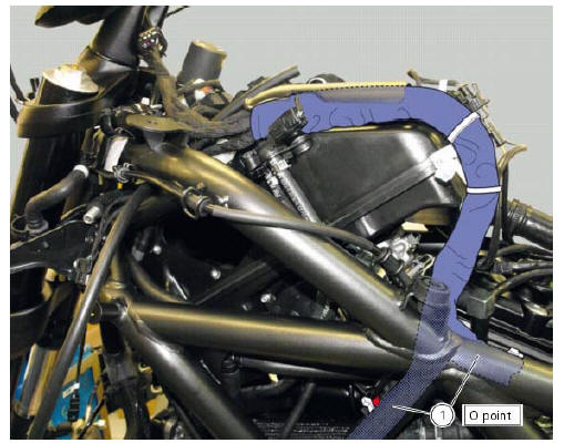
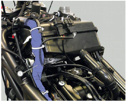
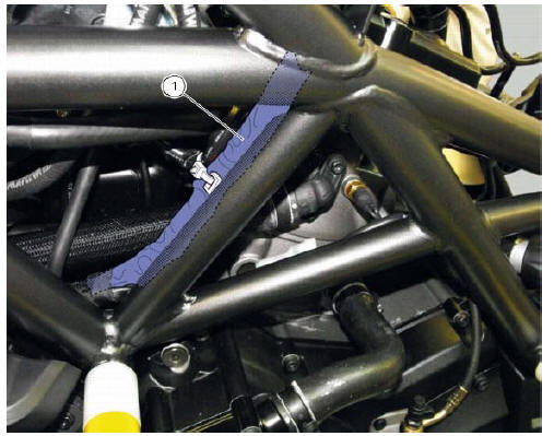
Table b
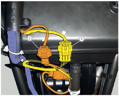
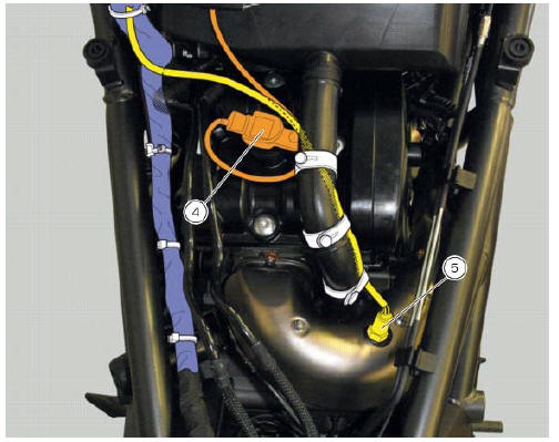
Table c
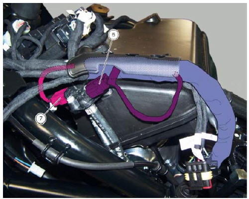
Table d
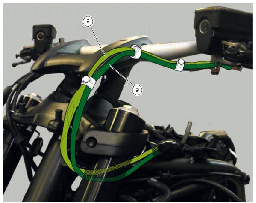
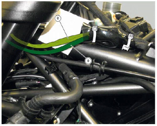
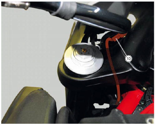
Table e
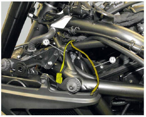
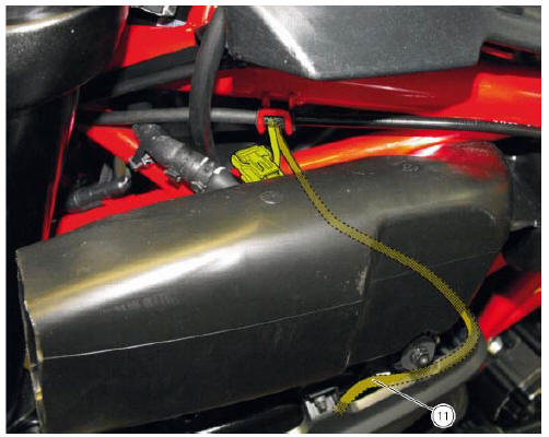
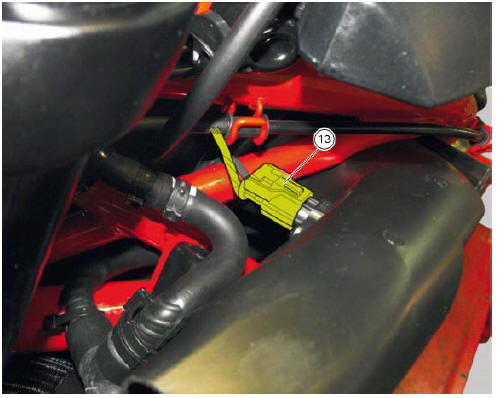
Table f
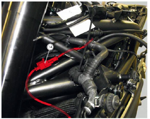
Table g
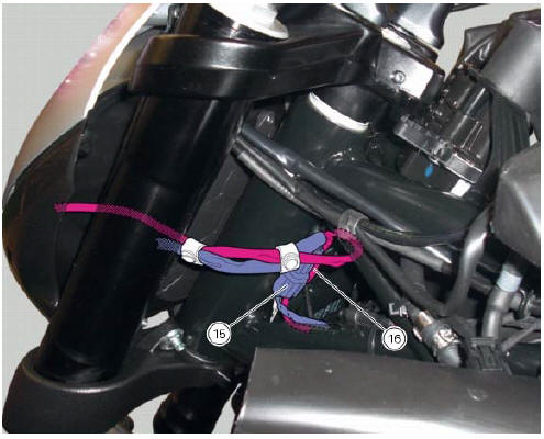
Table h
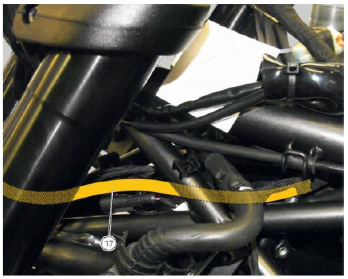
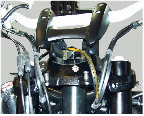
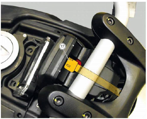
Table j
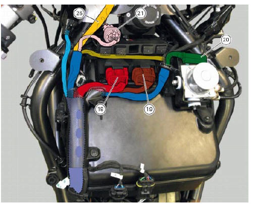
Table k
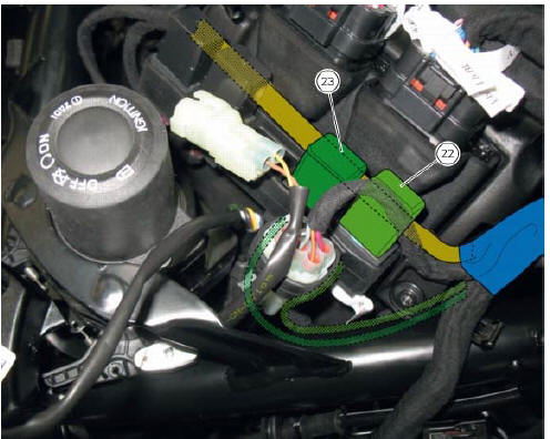
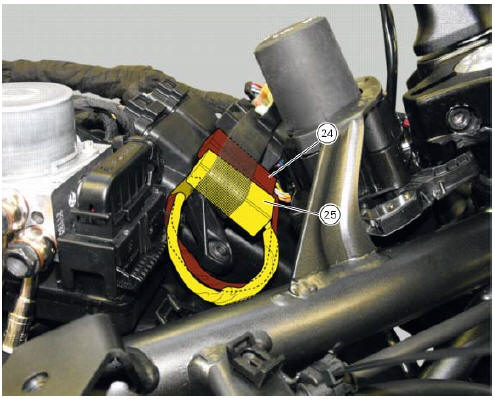
Table l
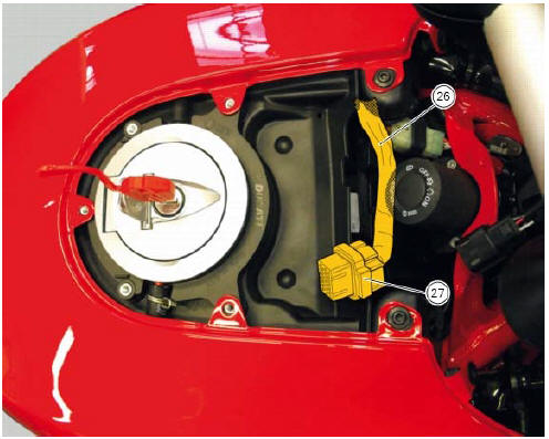
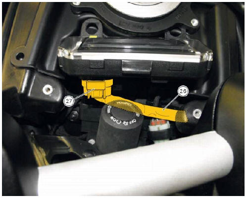
Table m
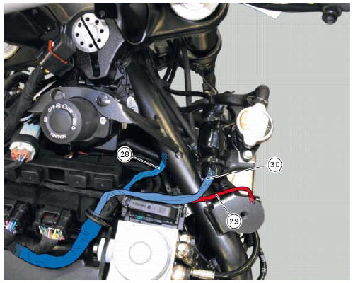
Table n
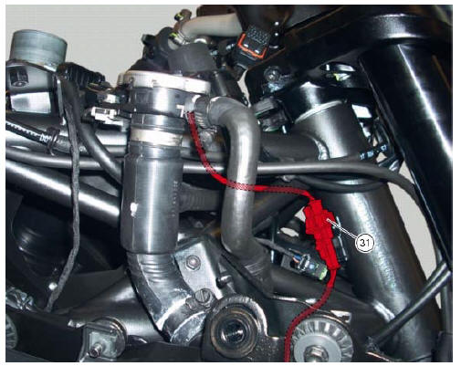
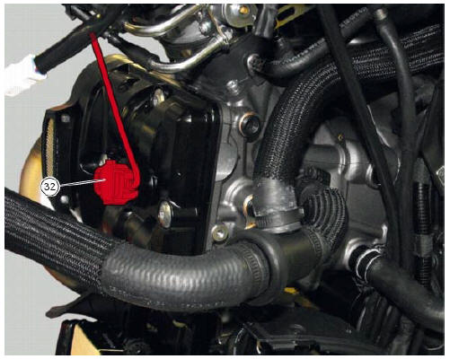
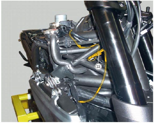
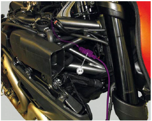
Table o
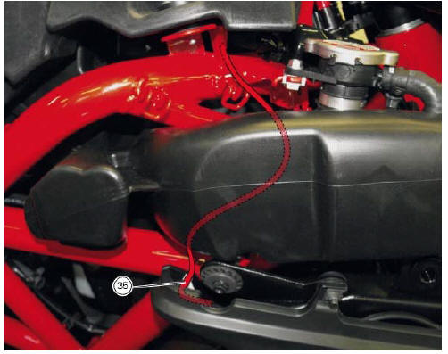
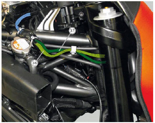
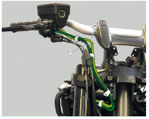
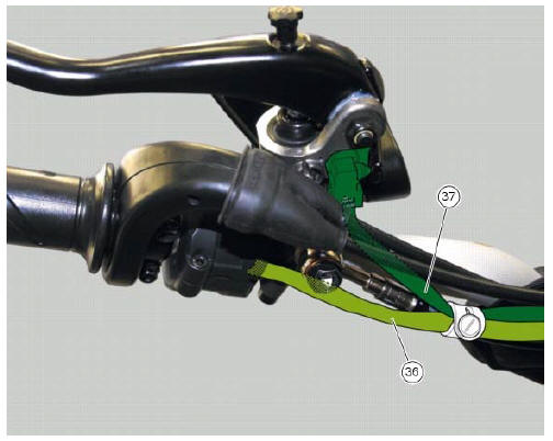
Table p
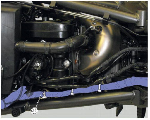
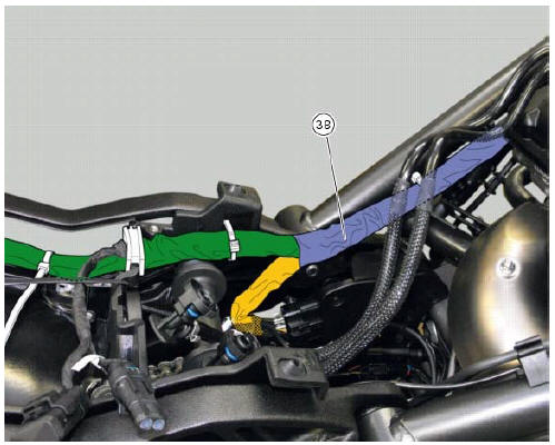
Table q
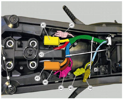
Table r
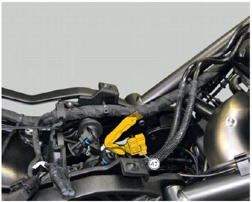
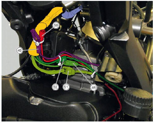
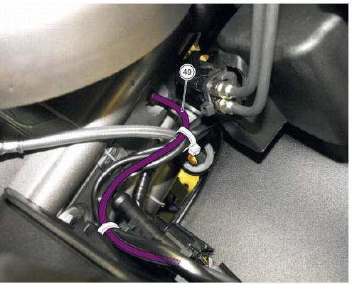
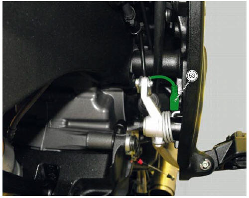
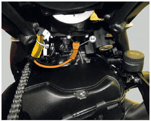
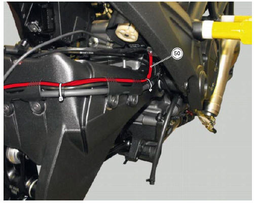
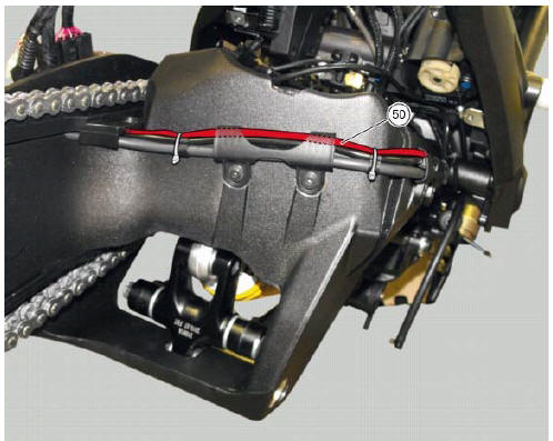
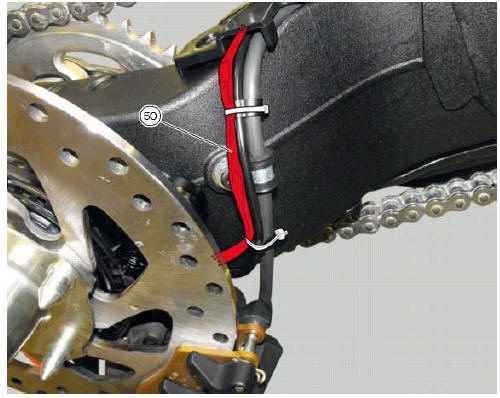
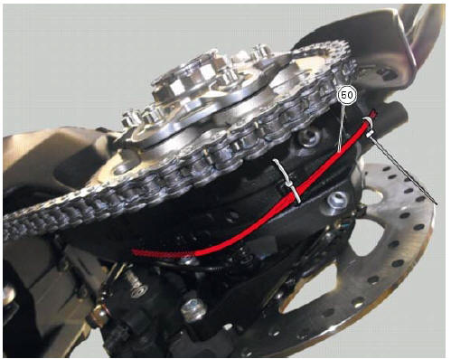
Table s
Table
t
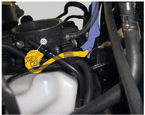
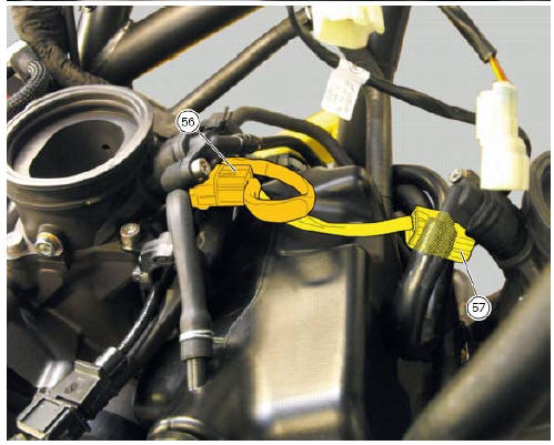
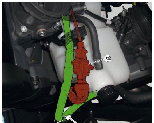

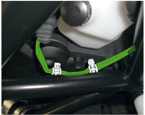
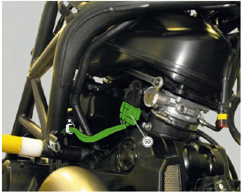
Table u
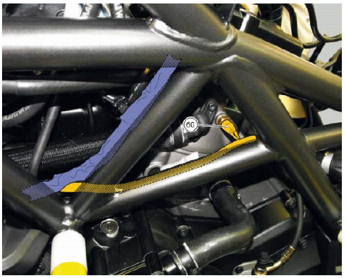
Table v

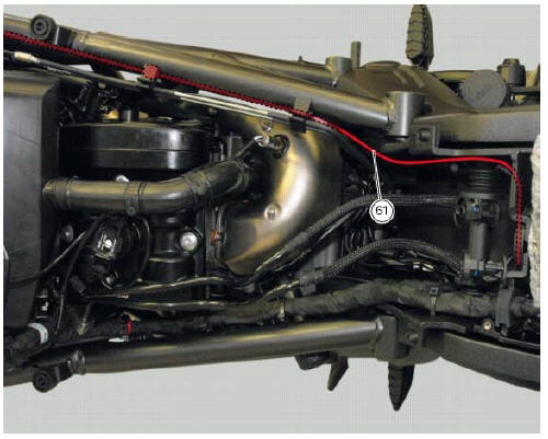
Table w

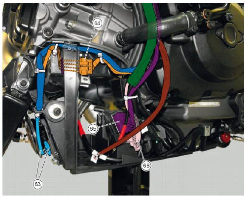
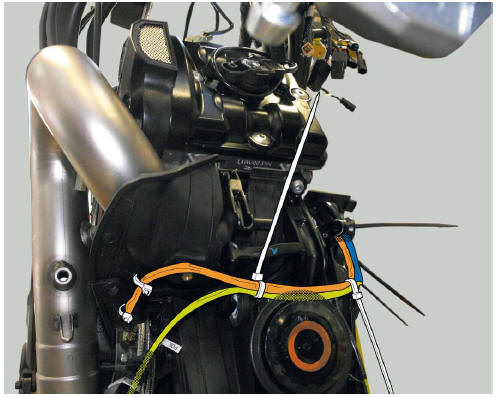
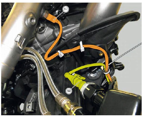
Table x

 Wiring diagram colour codes
B blue
Bk black
Bn brown
G green
Gr grey
Lb light blue
O orange
P pink
R red
V violet
W white
Y yellow
Rear left fuse box (1) key
Rear right fuse box (2) key
...

Other materials:
Introduction to the engine control system
The engine control system used on the diavel consists of the following
elements:
Ride-by-wire system (motorised throttle valves with electric actuator,
throttle grip position sensor and throttle valve
position sensor)
One injector per cylinder installed downstream of throttle valve
On ...
Low beam lights not working
Location of connections and components
(A) injection relay; (b) etv relay (throttle valve operating engine); (c)
radiator fan relay; (d) hands free relay.
Fuses located at the rear left of the vehicle.
(1) 10A dashboard; (2) 5a engine control unit; (3) 15a key-sense; (4) 20a
injecti ...
Pre-ride checks
Warning
failure to carry out these checks before riding, may
lead to motorcycle damage and injury to rider and passenger.
Before riding, perform a thorough check-up on your bike as
follows:
Fuel level in the tank
Check the fuel level in the tank. Fill tank if needed (page 140).
Engine oil le ...