
Ducati Diavel Service Manual: Running lights not working
Fault codes
Dds: no fault code displayed.
Dashboard: no fault code displayed.
Location of connections and components

(A) low / high beam and parking light connections rear running light and stop light connection.
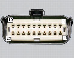
Pin numbering of wiring harness side bbs unit connection.
Checks
The front and rear parking lights use led light units and receive a 12 v power supply. Power the parking lights with an external 12 v power supply to test function (connect correctly as indicated in the wiring diagram).
Check congruence of the ground connection on the running lights.
Check that the parking lights receive 12v arriving from pin 7 of the bbs.
Check the integrity of the electrical circuit and connections (short-circuits to ground, short-circuits to vdc, open circuits).
If none of the aforementioned tests identifies the problem, replace the bbs.
Note
Check integrity of electric circuit - short-circuit to vdc = with dashboard on, using a voltmeter, a voltage is measured between the wire tested and ground.
Check integrity of electric circuit - short-circuit to ground = with the battery cables disconnected, using an ohmmeter, continuity is detected between the wire tested and ground.
Check integrity of electric circuit - open circuit = with the battery cables disconnected, using an ohmmeter, no continuity is detected between the two ends of the wire tested.
 Number plate light not working
Fault codes
Dds: no fault code displayed.
Dashboard: no fault code displayed.
Location of connections and components
Location of rear turn indicator and number plate light connection.
p ...
 Dashboard menu option scrolling not possible
Fault codes
Dds: no fault code displayed
Dashboard: no fault code displayed
Location of connections and components
Location of left hand handlebar switchgear set connection.
Pin numbering ...
Other materials:
Refitting the oil pump
If removed, apply specific threadlocker on the bushing (7) outer thread, and
screw it in the crankcase half, observing the
height.
Position the reference bushings (15) and the oil sealing o-rings (2) and (4)
according to the crankcase lubrication
channels.
Position the oil pump on th ...
Operating principle of dtc
The bbs receives the front and rear speed information from the abs over the
can. Then, the bbs sends the vehicle speed
information to be displayed on the dashboard over the can.
If the tangential speed of the rear wheel exceeds the tangential speed of the
front wheel by a given percentage, t ...
How to use this manual
How to use this manual
This manual has been prepared for technical personnel at ducati authorized
service centres with the aim of providing
fundamental information on how to work in accordance with the modern concepts of
"best practice" and "safety in the
workplace" during the maintenance, re ...