
Ducati Diavel Service Manual: Separation of the crankcase halves
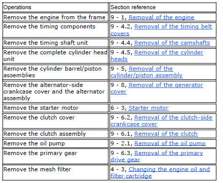
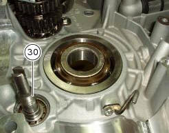
Use two screwdrivers to remove the circlip (29) from the timing belt driveshaft shaft (30) on the clutch-side crankcase half.
Note
Take care to avoid scoring the surface of the shaft while removing the circlip.
Unscrew the crankcase half screws on the chain side.
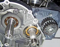
Unscrew the two screws (12) on the clutch side near the vertical cylinder.
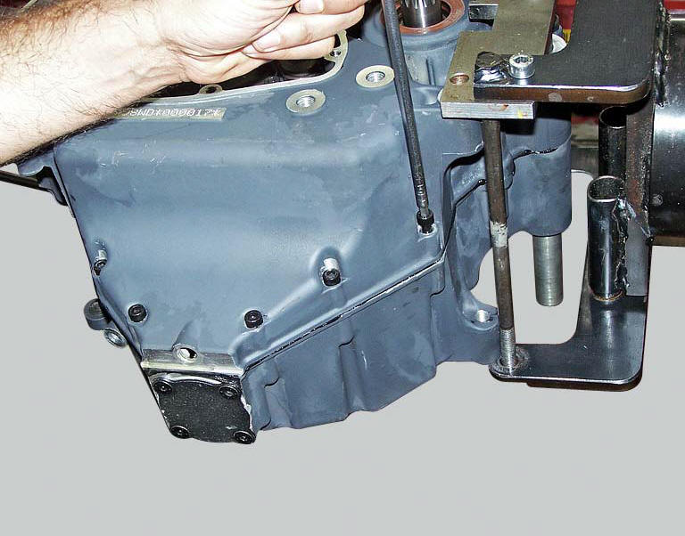
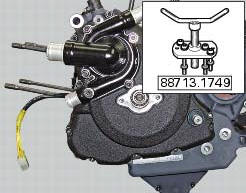
Reuse the alternator cover or a service cover with puller 88713.1749 Fitted. Secure cover to crankcase half with some of the original screws and begin separation by turning the central pin of the tool.
Tap the end of the gearbox secondary shaft with a plastic mallet to separate the crankcase halves.
Note
Take care not to lose the shims on the shafts and on the selector drum.
Remove gearbox shafts and gearbox selector drum from the crankcase halves (sect. 9 - 7.2, Removal of the gearbox assembly.
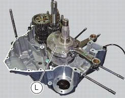
Drive out the crankshaft (l) using a plastic mallet, taking care not to lose the shims.
Remove the timing belt driveshaft (30).
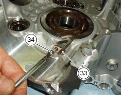
Remove the screws (34), remove the pipes (33) and collect the o-rings (32).
 Crankcase halves
Bearing
Bearing holder bushing
Alternator-side crankcase half
Bearing
Circlip
Washer
Bearing
Sealing ring
Bearing
Retaining plate
Screw
Screw
Clutch-side crankcase half
...
 Overhaul of the crankcase halves
Carefully examine the engine crankcase halves.
Check that the surfaces of the crankcase halves are perfectly flat using a
reference surface.
Check that the bearings (1) and (18), and the bushing ...
Other materials:
Setting menu
This menu is used to enable/disable and set some
motorcycle functions.
To access the "setting menu" press the button (2, fig. 14)
? for 3 seconds.
Note
When within this menu no other function can be
displayed.
Important
For safety reasons, the setting menu can only be
ac ...
Trip 1 meter
This function shows the distance travelled since the trip meter was last
reset (in km or miles depending on the specific
application).
Press and hold (1) "s" for 3 seconds while in this function to reset the trip
odometer.
When the reading exceeds 9999.9, Distance travelled is reset and t ...
Replacing the rear phonic wheel sensor
Disconnect the rear abs sensor (5) connector (c) from the main electric
wiring.
Open all the retainer clamps of the rear abs sensor cable (5): refer to table of
sect. 7 - 6, Flexible wiring/hoses
positioning.
Remove the rear abs sensor (5) from its seat on the rear calliper mounting ...