
Ducati Diavel Service Manual: Solenoid starter
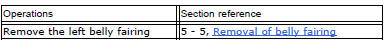
Remove the protection cover (a).
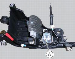
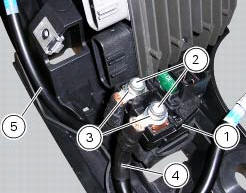
Undo the screws (2), taking care to collect the spring washers (3).
Remove the starter motor-solenoid cable (4) and the solenoid-battery cable (5).
Remove the starter solenoid (1) sliding it upwards.
Checking operation of the starter solenoid
To check the solenoid starter proceed as indicated in sect. 6 - 8, "Starter motor relay".
Ensure that the terminals are not oxidised.
Position the solenoid-starter motor cable (4) and the solenoid-battery cable (5) on the solenoid terminals.
Start the screws (2) fitting the spring washers (3).
Tighten the screws (2) to a torque of 4 nm +/- 10% (sect. 3 - 3, Frame torque settings).
Apply waterproof spray in the area of the screws.
Fix the starter solenoid (1) to the battery support inserting it in the tongues (b).
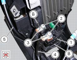
Refit the protection cover (a) inserting it on the solenoid starter guides until it engages with the tabs on both sides of the solenoid starter.

 Starter motor
Power:
0.7 Kw/12 v
Direction of rotation:
counter clockwise viewed from power take-off side.
The starter motor is highly compact and reliable and therefore rarely gives
any type of problem. ...

Other materials:
Removal of the throttle twistgrip
Peel back the rubber sleeve (a) protecting the throttle control cables.
Undo the screws (b) of the throttle grip (6) and open the command.
Disconnect the throttle grip cables (10) by unhooking the cable ends (c) from
their seats.
Remove the throttle twistgrip (6) from the handlebar.
...
Removing of the abs control unit
Drain the hydraulic fluid that is inside the front and rear braking system
tubes by disconnecting them from the master
cylinder and the calliper (sect. 4 -3, Changing the brake fluid).
Disconnect the connector (a) of the abs control unit (6).
Loosen the screws (16) that retain the abs ...
Scheduled maintenance chart
Operations to be carried out by the dealer
List of operations to be performed at 1000 km
Reading of the error memory with dds on the engine control units, vehicle and
abs
Change the engine oil
Change the engine oil filter
Check the indicators and lighting
Check the safety devices (side stand ...