
Ducati Diavel Service Manual: Steering head: front fork
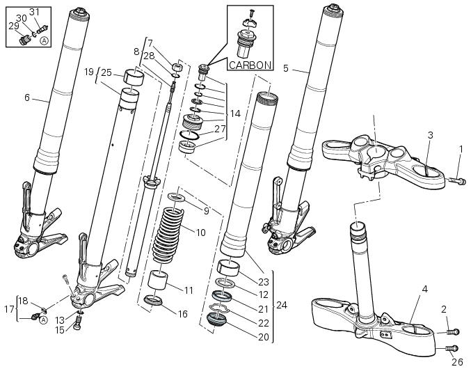
- Screw
- Screw
- Steering head
- Bottom yoke
- Left fork leg assembly
- Right fork leg assembly
- Counter nut
- Damper assembly
- Bush
- Spring
- Preload tube
- Collar
- Washer
- Top cap assembly
- Screw
- Washer
- Adjuster screw
- Special washer
- Fork tube + calliper unit
- Dust cap
- Sealing ring
- Circlip
- Upper bush
- Outer tube
- Lower bush
- Screw
- O-ring
- o-ring
- Special screw
- O-ring
- Adjuster
Spare parts catalogue
Diavel abs front forks
Diavel abs handlebar and controls
Diavel carbon abs front forks
Diavel carbon abs handlebar and controls
Important
Bold reference numbers in this section identify parts not shown in the figures alongside the text, but which can be found in the exploded view diagram.
 Fork
Fork
...
 Removal of the front forks
Before removing the front forks, it is first necessary to remove the
following parts:
Loosen the clamp screws (1) holding the fork legs to the steering head (3).
Loosen the clamp screws (2) and ...
Other materials:
Refitting the air filters
Apply universal sealant in the air duct (2) and (6) groove (d).
Fit seal (7) in the groove (d) having care to place it correctly in the relevant
seat so as to avoid abnormal wrinkles.
Pull out the filter cartridge (1) from the seat in the airbox.
Position the rh air duct (2).
Start ...
Topping up the electrolyte
Warning
Before carrying out any operations on the battery, keep in mind the
safety standards (sect.1 - 3, General safety rules).
The electrolyte in the battery is toxic and can cause burns if it comes into
contact with the skin because it contains
sulphuric acid. Wear protective clothing, a ...
How to use this manual
How to use this manual
This manual has been prepared for technical personnel at ducati authorized
service centres with the aim of providing
fundamental information on how to work in accordance with the modern concepts of
"best practice" and "safety in the
workplace" during the maintenance, re ...