
Ducati Diavel Service Manual: Symbols - abbreviations - references
To allow quick and easy consultation, this manual uses graphic symbols to highlight situations in which maximum care is required, as well as practical advice or information. Pay attention to the meaning of the symbols since they serve to avoid repeating technical concepts or safety warnings throughout the text. The symbols should therefore be seen as an aid to memory. Please refer to this page whenever in doubt as to their meaning.
The terms right-hand and left-hand refer to the motorcycle viewed from the riding position.
Warning
Failure to comply with these instructions may put you at risk, and could lead to severe injury or even death.
Important
Failure to follow the instructions in text marked with this symbol can lead to serious damage to the motorcycle and its components.
Note
This symbol indicates additional useful information for the current operation.
Text references
References in bold type indicate a part that is not illustrated in the figures next to the text, but which can be found in the exploded views at the beginning of each chapter.
References in non-bold type indicate a part that is illustrated in the figures alongside the text.
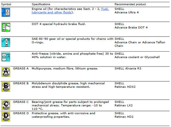
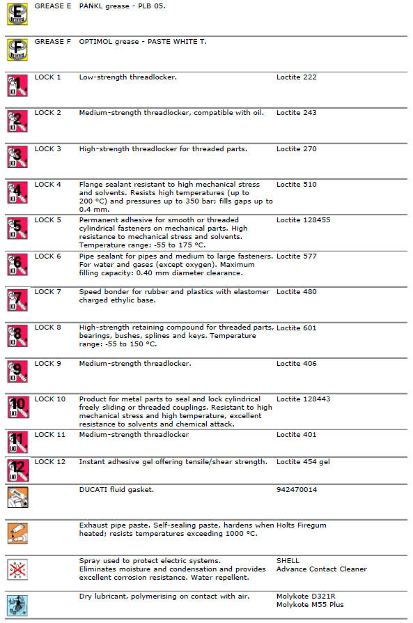
Product specifications
Symbols in the diagram show the type of threadlocker, sealant or lubricant to be used at the points indicated. The table below shows the symbols used and the specifications of the various products.

 How to use this manual
How to use this manual
This manual has been prepared for technical personnel at ducati authorized
service centres with the aim of providing
fundamental information on how to work in accordance wit ...

Other materials:
Airbox - throttle body
Airbox
O-ring
Injector
Throttle body assembly
Screw
Clamp
Intake manifold
Screw
Pressure sensor
Screw
Clamp
Hose
Sealing washer
Intake manifold
Sealing washer
Screw
Screw
Spacer
Bracket
Rubber pad
Clamp
Hose
Clamp
Union
Washer
Hose
Cable gro ...
Refitting the rear wheel
Lubricate the wheel shaft threaded end with prescribed grease.
Insert the wheel shaft by matching (a) with pins (b).
Install spacer (3) with the conical surface faced to the wheel conical
surface, washer (2), apply prescribed grease to nut
(1) and insert it by hand (1).
Tighten the ...
Battery
Battery safety rules
Warning
Before carrying out any operations on the battery, keep in mind the
safety standards (sect. 1 - 3, General safety rules).
When under charge, batteries produce explosive gases. Keep batteries away from
heat sources, sparks or open flames.
Instructions for use
T ...