
Ducati Diavel Service Manual: Testing the battery charging system
Note
The on-screen icons used during this procedure are explained in a table at the end of this section.
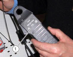
You can determine the engine rpm required for generator to produce just enough current to charge battery, feed the injection ignition system and all electric items fitted to motorcycle. When applied to a cable, the clamp-type amperemeter (1) part no. 88765.1126V detects the magnetic field generated by the current passing through that cable.
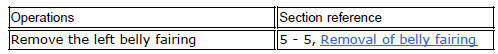
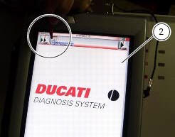
Turn on the dds diagnosis instrument (2) referring to the paragraph "tester power supply".
Connect the power and diagnosis cable (measurement module) (3) part no. 97900.0222 To the measurement module connector (d) of the dds (2).
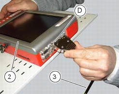
Connect the clamp-type amperemeter (1) to the connector (e) of the power and diagnosis cable (measurement module) (3).
Warning
The clamp-type amperemeter must not be connected to wires through which electrical current is flowing.
Insert the clamp-type amperemeter into the battery positive terminal lead with the arrow on the clamp pointing towards the battery positive terminal (+).
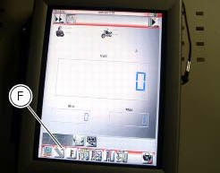
On the dds diagnosis instrument (2), select the "measurement module" function by pressing the corresponding icon; then press the "ammeter" icon (f) followed by the "start" icon.
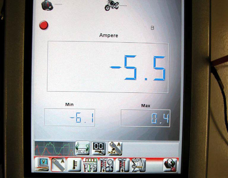
The socket to which the cable (measurement module) (3) is to be connected is indicated on the screen with a capital letter: a, b or c.

If the measured current is a positive quantity, it means that generator is feeding all electric items and charging battery at the same time. If the current has a negative sign, this means that the charging system is not able to power the electrical loads and a significant amount of the current required must be supplied by the battery, which is therefore discharging.
Important
If polarity is reversed when clamping the ammeter onto the cable, the sign of the readings will also be reversed, giving rise to incorrect diagnosis.
 Guided diagnosis
Note
The on-screen icons used during this procedure are explained in a table at
the end of this section.
The dds diagnosis instrument guides the operator step-by-step through the
various diagnos ...
 Deactivating the service indication on the dashboard
The message "serv" is displayed on the dashboard, indicating that the
motorcycle should be serviced in accordance with
the programmed maintenance plan. This indication is activated after the first ...
Other materials:
Refitting the rear-view mirrors
Start the screws (2) in their thread on the rear-view mirrors (1), inserting
the washers (4) as shown in the picture.
Insert the rear-view mirrors (1) in the u-bolts (3).
Tighten the screws (2) to a torque of 25 nm +/-10% (sect. 3 - 3, Frame torque
settings).
Warning
The left rear-view ...
Reassembly of the timing pulleys
Fit the pulley (11) on the flange (24), aligning the timing mark (d) on the
pulley with the timing mark on the (e) on the
flange.
Install the washer (23) up against the pulley, aligning the timing notch (f)
with the timing marks on the pulley and the
flange.
Insert the three screws (22) ...
Removal of the rear brake disc
Remove the rear eccentric hub (sec. 7 - 13, Removal of the rear wheel
eccentric hub and rear wheel shaft).
Undo and remove the four fixing screws (13) of the brake disk to the wheel axle
and remove the rear brake disk (14).
Loosen the four screws (24) and remove the rear phonic wheel (25). ...