
Ducati Diavel Service Manual: Tft - parameter setting/display
Warning
Any adjustments to the dashboard must only be carried out when the motorcycle is stationary. Never operate the dashboard controls while riding the motorcycle.
At the end of the check, the dashboard always displays as the "main" indication the odometer (tot) on the left and the average fuel consumption on the right (unless menu 2 was disabled).
At the end of the initial check, the dashboard will always show the "main" display, indicating the following information: set "riding style" (riding mode); gear indication (gear); menu 1: odometer (tot); menu 2: average fuel consumption (cons. Avg).
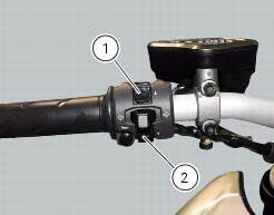
By pressing the button (1) "s" it is possible to switch to the following functions of menu 1: trip1 - trip meter 1; trip2 - trip meter 2; trip fuel - distance travelled on fuel reserve (only if active); by pressing the button (2) "t" it is possible to switch to the following functions of menu 2: cons. - Current fuel consumption; speed avg - average speed; trip time - trip time; air - air temperature; menu 2 viewing can be disabled through the "menu 2" function of the setting menu.
 Dashboard on tank
Menu 1 (tot, trip1, trip2, trip fuel).
Menu 2 (cons.Avg., Cons., Speed avg, air and trip time) if active.
Gear / neutral indication.
Icon referred to the function below from menu 1.
Indicat ...
 Total distance covered indicator: "odometer"
This function shows the total distance covered by the vehicle (in km or miles
depending on the specific application).
At key-on the system automatically enters this function.
The odometer read ...
Other materials:
Refitting the timing belts
Rotate the pulleys on the timing belt driveshaft until the timing mark on the
outer roller is aligned with the mark on the
clutch-side crankcase cover.
In this condition, the horizontal cylinder piston will be at top dead centre.
Install in the alternator cover seat the tool code 88713.20 ...
Refitting the rear-view mirrors
Start the screws (2) in their thread on the rear-view mirrors (1), inserting
the washers (4) as shown in the picture.
Insert the rear-view mirrors (1) in the u-bolts (3).
Tighten the screws (2) to a torque of 25 nm +/-10% (sect. 3 - 3, Frame torque
settings).
Warning
The left rear-view ...
Appropriate diagnosis tools
97900.0211 Dds (ducati diagnosis system) without cables
97900.0227 Power cable and diagnosis
97900.0222 Power cable and diagnosis 1060838 (measurement module)
97900.0218 Vacuum sensor
552.1.039.1A Pressure sensor
97900.0220 Pressure/vacuum tube
97900.0221 Union
...