
Ducati Diavel Service Manual: The hands free module
Introduction
The hands free module incorporates the control unit communicating with the other nodes on the motorcycle, the on/off button, the microswitches detecting full lock steering angle (for enabling steering lock engagement) and the steering lock.
The module is sealed and its individual components cannot be accessed for diagnosis, repair or replacement.
Wiring diagram
No wiring diagram is available for the components integrated into the hands free module. For the main electric wiring see chapter ("wiring diagram of the hands free system") of this section.
Error codes
"Hands free diagnosis" error: "steering lock": a fault has been detected in
the electric steering lock system. The following
icon appears on the tank dashboard:
- If the error occurred while engaging or disengaging the steering lock, check that the handlebar is fully turned to the left or right and try to engage or disengage the steering lock again.
- If the error occurred while engaging or disengaging the steering lock, check that the lock pin can move freely and is unobstructed, then try to engage or disengage the steering lock again.
- If none of the tests described above identifies the problem, replace the hands free system.
"Hands free diagnosis" error: "eeprom state": fault detected in the internal
hands free system memory. The following
icon appears on the tank dashboard:
- Replace the hands free system
Electrical characteristics and checking component
No electrical characteristics or checking procedures are given for the hands free system as all components are integrated in the module and cannot be accessed for diagnosis, repair or replacement.
The module receives direct 12 volt battery power over pin 1 and via the main 30 a fuse.
Ground is on pin 2.
In the event of fault
In the event of any hands free system fault, the engine may switch off or engine start may not be possible.
In the event of a fault in the steering lock integrated into the hands free system occurring during either engagement or disengagement, the system will attempt to automatically retract the lock pin. If this fails, a low volume alarm signal is emitted by the hands free system.
Installation location
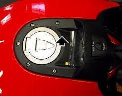
The plastic shield covering the hands free system is visible in the photo
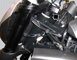
The hands free system on/off button is shown in the photo, with the plastic shield removed.
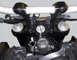
The lock pin of the electric steering lock is visible in the lower portion of the hands free system.
The photo shows the hands free system removed from the motorcycle fuel tank. One of the two switches detecting the full lock handlebar steering position is indicated in the photo.
Component replacement methods
No special measures or reprogramming are necessary in order to replace the hands free system. However, the motorcycle keys must be reprogrammed after replacement. See chapter "programming/reprogramming keys"
 Wiring diagram of the hands free system
The diagram illustrates the inputs, outputs and communication lines used by
the hands free system.
1I - on/off button placed on the hands free system (located below the plastic
cover)
2I - o ...
 Communication antenna
Introduction
The communication antenna enables the hands free system to detect and
communicate with the active or passive key.
The active key is detectable within a range of 1.5 Metres, whereas ...
Other materials:
On/off switch on handlebar
Introduction
The on/off switch on the handlebar is used to switch the dashboard on and
off, if a key has been detected, and start the
engine.
With the switch turned to "run off" (centre position), pushing downwards
switches the dashboard on or off (activating
the button inside the switch). ...
Refitting the fuel tank
If the fuel tank has been disassembled into its component parts, reposition
all the parts as shown in the exploded view.
In particular:
tighten the screws (13) to a torque of 5 nm +/-10% (sect. 3 - 3, Frame torque
settings).
Refit the tank by inserting its rear side into the pin on the ...
Removal of the water pump
Note
For clarity, the figures show the engine removed from the frame.
Loosen and remove the water pump cover (12) fixing screws (13) to the
generator cover (16).
Remove the water pump cover (12).
Clean the pump housing of any scale. Check the bearings wear by turning the
impeller s ...