
Ducati Diavel Service Manual: Throttle valve actuator motor relay
Introduction
The throttle valve actuator motor is powered by the engine control unit. The engine control unit receives the necessary power from a specific relay.
Component assembling position
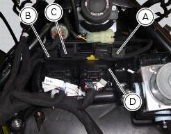
A injection relay; b etv relay (throttle valve actuator motor), c radiator fan relay, d engine control unit.
Connection wiring diagram
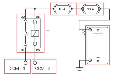
Ccm engine control connection, t throttle valve actuator motor relay. 85 Throttle valve actuator motor relay activation, light blue/green - lb/g, 87 ecu power input for throttle valve actuator motor, red/brown r/bn, 30 and 86 red/purple - r/v, r battery positive (+30).
In the event of fault
In the event of a throttle valve actuator relay fault, the ecu cuts motor power and the throttle valves close (see chapter operating principle and characteristics of the ride-by-wire system in this section).
Fault codes generated and possible correlated faults
Fault codes generated by the engine control unit and displayed by the dds (etv relay diagnosis):
- Throttle valve actuator motor relay malfunction (no specific fault indicated by dds): check integrity of the fuses, electrical circuit and electrical connections and check relay function. After removing from its mounting, apply 12 v power to pin 85 and pin 86 and check that pin 87 and pin 30 close (continuity between pins).
Note
Check integrity of electric circuit - short-circuit to vdc = with dashboard on, using a voltmeter, a voltage is measured between the wire tested and ground.
Check integrity of electric circuit - short-circuit to ground = with the battery cables disconnected, using an ohmmeter, continuity is detected between the wire tested and ground.
Check integrity of electric circuit - open circuit = with the battery cables disconnected, using an ohmmeter, no continuity is detected between the two ends of the wire tested.
The dashboard service display shows the error "etv relay" (throttle valve actuator motor relay) and the eobd warning light activates.
Possible correlated faults: the engine does not start, cuts out or remains running at idle speed and will not accelerate.
Check:
- Integrity of fuses.
- Relay function.
The throttle valve actuator motor may be actuated into one of the three preset positions (0%, 50%, 100%) using the dds. During motor actuation, the throttle valve actuator motor relay is driven.
If none of the tests described above identify the problem and the throttle valve actuator relay is in proper working order, contact ducati.
Component replacement methods
No special measures are necessary in order to replace the throttle valve actuator motor relay.
 Injection relay
Introduction
The fuel pump, injectors and ignition coils are all powered via the injection
relay. The relay also sends voltage to the
engine control unit, which enables activation of the relay its ...
 Starter motor relay
Introduction
When the rider presses the start button, with all the safety conditions
required to enable engine start met, the engine
control unit enables the relay that activates the starter motor ...
Other materials:
Checking brake and clutch fluid level
The levels should not fall below the min marks on the
respective reservoirs.
If the level is too low, air can get into the circuit, thus
impairing the efficiency of the system.
Brake and clutch fluid must be topped up and changed at the
intervals specified in the scheduled maintenance table ...
Removal of the swingarm
Before removing the parts in question, you must first carry out the following
operations:
Remove the rear wheel eccentric hub as described in chapter "removal of the
rear wheel eccentric hub and rear wheel
shaft" of this section.
Loosen screws (7) and remove the hose grommets (13), (15) ...
Indicator cons. Avg - average fuel consumption
This function indicates the "average" fuel consumption.
The calculation is made considering the quantity of fuel used and the km
travelled since the last trip 1 reset. When trip 1
is reset, the value is set to zero and the first available value is shown on the
display 10 seconds after the re ...