
Ducati Diavel Service Manual: Trip 1 meter
This function shows the distance travelled since the trip meter was last reset (in km or miles depending on the specific application).
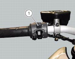
Press and hold (1) "s" for 3 seconds while in this function to reset the trip odometer.
When the reading exceeds 9999.9, Distance travelled is reset and the meter automatically starts counting from 0 again.
If the system measurement units are changed at any moment through the "units of measurement modification function" function of the setting menu, or if there is an interruption in the power supply (battery off), the distance travelled is reset and the count starts from zero (considering the newly set unit of measurement).
When this value is reset, also the "average fuel consumption", "average speed" and "trip time" functions are reset.
 Total distance covered indicator: "odometer"
This function shows the total distance covered by the vehicle (in km or miles
depending on the specific application).
At key-on the system automatically enters this function.
The odometer read ...
 Trip 2 meter
This function shows the distance travelled since the trip meter was last
reset (in km or miles depending on the specific
application).
Press and hold (1) "s" for 3 seconds while in this function ...
Other materials:
Removal of the brake discs
The front brake discs consist of an inner carrier, which is mounted to the
wheel, and an outer rotor. Both parts must be
changed together as a pair.
Remove the front wheel (sect. 7 - 1, Removal of the front wheel).
Undo the retaining screws (5) of the disc to the wheel, remove the disc (7) ...
How to turn the motorcycle off
To turn the motorcycle off, turn the switch from "run on" to "run off". The
engine stops. To switch the dashboard off,
push the on/off switch downwards. When released, the switch automatically
returns to the "run off" position.
Push the switch downwards to switch the engine off and enter " ...
Removal of the clutch-side crankcase cover
Unscrew the screws (2), (3) and (5) securing the clutch-side crankcase cover
(1).
Tap around the edge of the cover with a plastic mallet to detach it from the
crankcase half.
Remove the clutch cover (1) paying attention to the centring bushing (12).
Check the condition of the cent ...