
Ducati Diavel Service Manual: Turn indicators not working
Fault codes
Dds: no fault code displayed.
Dashboard: no fault code displayed.
Wiring diagram
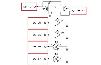
Db dashboard connection, bbs bbs unit connection, s turn indicator button, f1 front left turn indicator, f2 front right turn indicator, f3 rear left turn indicator, f4 rear right turn indicator. 2 On grey button - gr, 1 on red/blue button - r/b, 4 on black button - bk, db 26 white/black w/bk, db 25 green/black - g/bk, bbs 16 white/green - w/g, bbs 17 White/black w/bk.
Location of connections and components
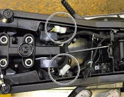
Location of rear turn indicator and number plate light connection.
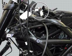
Location of left hand handlebar switchgear set connection.

Location of front right turn indicator connection.
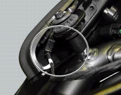
Location of front left turn indicator connection.
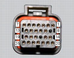
Pin numbering for wiring harness side dashboard connector.
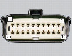
Pin numbering of wiring harness side bbs unit connection.
 Horn not working
Fault codes
Dds: horn diagnosis -> short circuit to ground (s.C. Gnd).
Dashboard: the error "claxon" (horn) is shown on the service display. The eobd
warning light activates.
Wiring diagram
...
 High beam flash not working - start/stop lap function not working
Fault codes
Dds: no fault code displayed.
Dashboard: no fault code displayed.
Wiring diagram
Db dashboard connection, s high beam flash button. 7 Orange - o, 1
red/blue - r/b.
Location of ...
Other materials:
Clutch lever
Lever (1) disengages the clutch. It features a dial adjuster (2)
for lever distance from the twistgrip on handlebar.
The lever distance can be adjusted through 10 clicks of the
dial (2). Turn clockwise to increase lever distance from the
twistgrip. Turn the adjuster counter clockwise to decrea ...
Replacing the tank flange and fuel sensor
Loosen the screws (19) securing the fuel tank flange (20).
Remove the flange (20) from the tank (20).
Recover the seal (21).
Undo and remove the two fixing screws (g) and move the protection (f).
Before reassembly, carefully remove any deposits or scale from all parts.
Note
The flang ...
Tester power supply
The dds (1) part number 97900.0215 Can be powered from the vehicle as
follows:
From the mains power supply: by connecting the power supply connector
(n) to the network power supply (2) part no.
97900.0224;
From the motorcycle: connecting the corresponding cables (see paragraph
...