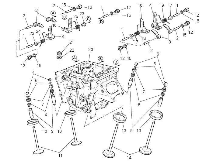
Ducati Diavel Service Manual: Valves - rocker arms

- Closing rocker arm shaft
- Opening rocker arm shaft
- Opening rocker arm
- Closing rocker arm (left)
- Valve opening shim
- Half rings
- Valve closing shim
- Sealing ring
- Valve guide
- Exhaust valve seat
- Exhaust valve
- Plug
- Intake valve seat
- Intake valve
- Aluminium gasket
- Closing rocker arm (right)
- Spacer
- Valve return spring (right)
- Valve return spring (left)
- Head
- Cylinder head nut
- Washer
- Spacer
- Valve return spring (right)
- Valve return spring (left)
Spare parts catalogue
Diavel abs crankcase halves
Diavel abs vertical cylinder head
Diavel abs horizontal cylinder head
Diavel carbon abs crankcase halves
Diavel carbon abs vertical cylinder head
Diavel carbon abs horizontal cylinder head
Important
Bold reference numbers in this section identify parts not shown in the figures alongside the text, but which can be found in the exploded view diagram.
- Removal of the cylinder heads
- Removing the valves
- Removing the valve rocker arms
- Overhaul of cylinder head components
- Reassembly of the cylinder head
- Refitting the cylinder head assemblies
 Refitting the intake manifold and coolant union
Apply prescribed threadlocker to the fitting (12), start it with seal (24)
and tighten it to a torque of 2.5 Nm (min. 2 Nm -
max. 3 Nm) (sect. 3 - 3, Frame torque settings).
Install the pipe (b) ...
 Removal of the cylinder heads
Using the tool code 88713.2676, Undo the nuts (21) on the cylinder head stud
bolts.
Remove the cylinder head nuts (21) and special washers (22).
Remove the cylinder head assembly by lift ...
Other materials:
Fuel tank
fuel tank
Rubber pad
Spacer
Screw
Hose
Tray
Y-fitting
Hose
Hose
Filler cap
Screw
Complete hose guide
Screw
Hose clip
Hose
Screw
Screw
Sealing washer
Screw
Flange
Sealing washer
Spare parts catalogue
Diavel abs fuel tank
Diavel abs fuel system
Diav ...
Lap activation/deactivation function (lap time)
This function activates and deactivates the lap function (lap
time).
To access the function it is necessary to view the "setting" menu page 48, using
button (1, fig. 14) ?"
" or (2, fig. 14) ?" " select the "lap" function and
press the reset button
...
Removing of the rear wheel
Place the motorcycle on the rear service stand and engage the 1st gear.
Remove the clip (6).
Using a suitable socket wrench, loosen the wheel nut (1).
Fully unscrew the nut (1), then remove the washer (2) and the spacer (3).
Remove the rear wheel from the motorcycle.
...